1 Year Warranty
Description
Overview
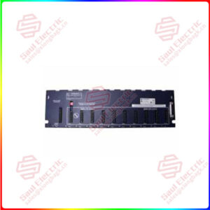
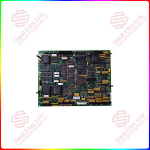
Essential details:VMIVME-3215 High-Performance 16-bit Analog-to-Digital Converter Board
The VMIVME-3122 is a member of VMIC’s extensive family of analog input/output products for the VMEbus. With 16-bit digitizing resolution, program-controlled gain, selectable conversion rate, and automatic scanning of 64 differential or single-ended analog inputs, the VMIVME-3122 provides exceptional dynamic range and analog input channel density. Various operating modes are supported, including autoscanning, data bursts and external synchronization. This board is designed to interface directly with VMIC’s line of signal conditioning boards for digitizing the outputs from thermocouples, RTDs and strain gages.
Individual channel gains can be downloaded for use during scanning operations, or the board can be configured with a fixed gain that is common to all channels.
Multiple boards can be synchronized together to enable as many as 16 boards to initiate each scan simultaneously. An Interval Timer, Bus Interrupter, Channel Counter and Midscan/Endscan flag simplify the monitoring of data within the dual port data buffer. The system applications that can benefit from the VMIVME-3122 capabilities include factory automation, process control, data acquisition systems, training simulators and laboratory instrumentation.
The following brief overview of principal features illustrates the flexibility and performance that is available with the VMIVME-3122:
• 16, 32 or 64 differential or single-ended analog inputs
• 16-bit A/D conversion
• 381 Hz to 100 kHz selectable scanning rate for high-performance option, 381 Hz to 50 kHz for standard performance option
• Programmable gains of x1 or x10
Features of the VMIVME-3122 (Continued):
• A/D converter ranges of ±2.5 V, ±5 V, ±10 V, 0 to +5 V, 0 to +10 V
• Programmable channel gains
• 16- to 1,024-word dual port data buffer
• Operation in short I/O (A16), standard (A24), or extended (A32) data space
• Programmable channel block size and buffer size
• Optional low pass input filters
• Continuous and burst operating modes
• Free running operation or external/internal triggering
• Bus interrupter for Midscan or Endscan indication
• Programmable interval timer for timed data bursts
• Direct cabling from VMIC signal conditioning boards
• Initializes after a reset in autoscan mode with gain = x1
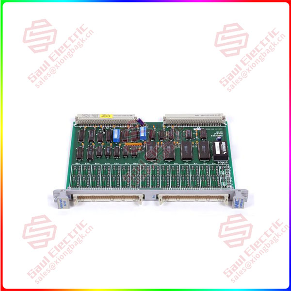
VMIVME-3210
lf you need to inquire or purchase ,please send the product models to my email or call medirectly .
sunny He
[Email] sales@xiongbagk.cn
[Mobile] 86-18059884797
[WhatsApp] 86-18059884797
[Skype] sales@saulcontrol.com
VMIVME-3215 High-Performance 16-bit Analog-to-Digital Converter Board
The VMIVME-3122 (Figure 1 on page 15) is a high-resolution, 16-bit, 64-channel Analog Scanning and Digitizing Input board for VMEbus system applications. Dual-ported data memory, on-board timers, automatically controlled gain and a programmable bus interrupter enable the VMIVME-3122 to support extensive analog input traffic, with minimum involvement of the host processor.
Analog inputs are scanned and digitized sequentially. The digital values are stored in a dual port data buffer which can be accessed at any time from the VMEbus. The gain of each channel can be programmed individually, or can be set in software for a fixed gain that is common to all channels. Channel gain is software selectable as x1 or x10. A/D converter voltage ranges are jumper-selectable for ±2.5 V, ±5 V, ±10 V, 0 to 5 V and 0 to 10 V.
When a system or program reset occurs, the board initializes in the 64-channel autoscanning mode at a rate of 100 KHz and all channel gains are initialized to unity (x1). After a reset operation, the program can select the timed burst or triggered burst modes, and can modify the block size, buffer size, and channel gains as necessary.
The channel block is adjustable as 1, 8, 16, 32 or 64 channels, and the data buffer size can be selected from 16 to 1,024 data words in binary increments.
When in standard performance mode, the board must be reprogrammed after reset for the 50 kHz scanning rate. A value of $00F7 must be written to relative address $0006.
Timed data bursts are controlled by an interval timer which can provide repetitive or single-shot burst intervals of up to 687 sec. A burst can consist of from 8 to 1,024-channel samples. A data ready flag is available at the middle or end of a scan, and an interrupt request can be generated simultaneously with the flag. The interrupt can also be initiated after a specific number of samples have been acquired.