1 Year Warranty
Description
Overview
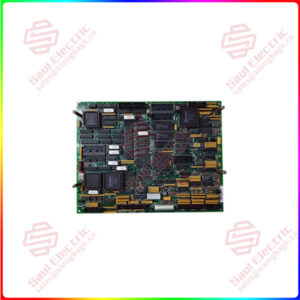
Essential details:VME-PMC-CADDY VME-Carrier Board for 2 PMC Modules
Product Description
Easy Expansion of VMEbus Systems
- Adds up to 2 PMC modules to a VMEbus system
- All PMC I/O signals are routed to the VMEbus connector P2
- Suitable for two PMC modules in single width or one module in double width according to IEEE P1386/ draft 2.0 specification
- Optionally available with alternative P2 pinout ( VME-PMC-CADDY-32P2 )
High Bandwidth Connection between VME and PCI
- Powerful VME PCI bridge UNIVERSE CA91C142
- 4-level VME arbiter, address space up to A32/D32
- VME64 expansion connector
- Master or slave functionality
Reliable design – easy to handle and cost effective
- Designed for low power consumption and easy cooling
- Proven in many different industrial applications
- Standard interface and form factors according to IEEE P1386 and IEEE 1014 Rev. D
- Software libraries available
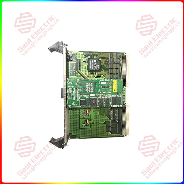
VME-PMC-CADDY
lf you need to inquire or purchase ,please send the product models to my email or call medirectly .
sunny He
[Email] sales@saulcontrol.com
[Mobile] 86-18059884797
[WhatsApp] 86-18059884797
[Skype] sales@saulcontrol.com
VME-PMC-CADDY VME-Carrier Board for 2 PMC Modules
VME-PCI Link
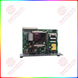
The VMEbus assembly VME-PMC-CADDY is a VME64 base board for accommodating up to two PMC modules in single size or one module in double size. The VME-PCI bridge UNIVERSE II CA91C142 from Tundra with an internal clock rate of 33 MHz is used for connection to the VMEbus.
VMEbus Interface
The design of the CA91C142 allows the board to be operated as a slave or also as a master on the VMEbus. As master the board supports a 4-level arbiter. The VME-PMC-CADDY operates with a data width of up to 32 bits and with 32 address signals on the VMEbus.
The VMEbus interrupt can be placed on any of the seven interrupt request lines. The connection to the VMEbus is made via two 160-pin VG connectors according to IEC 603-xx in accordance with the VME64 extension. An active VMEbus interrupt request is indicated by a red LED and a VMEbus access to the board by a yellow LED in the front panel.
PMC Plug-In Units
The two PMC slots are designed according to the draft standard IEEE P1286/Draft 2.0 (except for the standard I/O pin routing). All commercially available PMC modules can be fitted. In addition to the transfer connectors for the PMC address/data and control signals, each slot of the VME-PMC-CADDY is equipped with an I/O connector that routes the I/O signals of the PMC modules to the VMEbus connector P2.
Two different P2 pin assignments are available: In the default configuration, each P2 pin is connected to only one I/O pin of the PMC modules (as per PMC update of FORCETM, Table 1, Author: Wayne Fischer, Director of Strategic Programs CMC/PMC Working Groups Chair, 10/22/96).
In the option ‘-32P’ the pin assignment is carried out according to IEEE P1386/Draft 2.0, Table 6-3. This pinout allows the connection of two PMC modules via P2, since some of the PMC I/O signals are collocated on the P2.
Front panel
The front panel of the VME-PMC-CADDY is provided with two knockouts for the front panels of the PMC modules. A blind cover for unoccupied slots is included.