Synchro-check relay for checking the conditionsat circuit breaker closing
One synchro-check relay is capable ofcheckingthe close conditions of two separate circuitbreakers.
Synchro-check function for checking synchro-nism when live lines/busbars are to be connectedtogether.
Voltage-check function for checking energizingconditions. Four energizing directions selectablefor each circuit breaker.
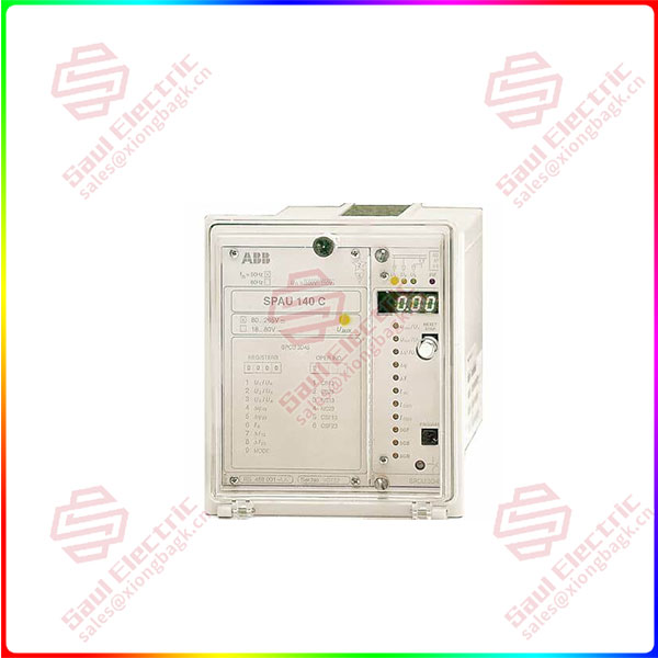
Essential details:SPAU140C SPAU 140 C Synchro-check relay
Synchro-check relay for checking the conditionsat circuit breaker closing
One synchro-check relay is capable ofcheckingthe close conditions of two separate circuitbreakers.
Synchro-check function for checking synchro-nism when live lines/busbars are to be connectedtogether.
Voltage-check function for checking energizingconditions. Four energizing directions selectablefor each circuit breaker.
Two control modes available: continuous modeoperation for applications where the synchro-check relay gives the close permission to anothermodule (e.g. the control module) and commandmode operation for applications where the re-lay closes the circuit breaker via its own controloutput.
Alarm signal for failed CB closing at commandmode operation
Continuous self-supervision of both hardwareand software
Serial port for connecting the relay to the elec-trical or optical SPA bus
The relay incorporates two identical stageswhich operate as independent units. Both stagesof the synchro-check relay has two parallel functions: a synchro-check function and a voltagecheck function.
The synchro-check relay can be used for twodifferent operating conditions, the most typicalof which is where both sides of the circuitbreaker to be closed are live. Then synchronismis always checked before the circuit breaker isgiven the permission to close. The other situa-tion is where one or both sides of the circuitbreaker to be closed are dead and, consequentlyfrequency and phase difference cannot be meas-ured. In this case the relay checks the energiz-ing direction. The user is able to define the volt-age range within which the measured voltage isdetermined to be “live” and “dead”.
The purpose of the synchro-check function isto find the instant when the voltages on bothsides of the circuit breaker are in synchronism.The conditions for synchronism are met whenthe voltages on both sides of the circuit breakerhave the same frequency, are in phase and are ofsuch a magnitude that the concerned busbarsor lines can be regarded as live.
SPAU140C
lf you need to inquire or purchase ,please send the product models to my email or call medirectly .
sunny He
[Email]sales@xiongbagk.cn
[Mobile]86-18059884797
[WhatsApp] 86-18059884797
[Skype]sales@saulcontrol.com
SPAU140C SPAU 140 C Synchro-check relay
The voltage-check function checks the energizing direction, Energizing is defined as the situ-ation where a dead network part is connectedto an energized section ofthe network.The con-ditions ofthe network sections to be controlledby the circuit breaker, i.e. which side has to belive and which side dead, are determined by set.ting. A situation where both sides are dead ispossible as well.
When the energizing direction corresponds tothe settings, the situation has to be constant fora certain time before the close signal is permit-ted.The purpose ofthis operate time (dead time)is to make sure that the dead side remainsdeenergized and that the situation is not due toa temporaryinterference. Should the conditionsnot persist for the specified operate time, theoperate time is reset and the procedure is startedagain when allowed by the conditions. Not un-til the required energizing situation has beenconstant throughout the set operate time, cir-cuit-breaker closing is permitted.
Stage 2 of the synchro-check relay can be blocked by applying an external auxiliaryvoltage level blocking signal BS to terminals 22-23. The blocking function is se-lected with switch 2 of switchgroup SGB in the main menu of the relay. Theblocking function is not activated in the default setting of the relay.
When command mode operation has been selected for stage l, the stage is acti-vated for CB closing by an auxiliary voltage level control signal CS13, applied tothe terminals 45-46. If continuous mode operation has been selected no controlsignal need be applied to the relay. Switch 3 ofswitchgroup SGB is used for select-ing the desired mode of operation, Default setting of stage 1: continuous modeoperation.
When command mode operation has been selected for stage 2, the stage is acti-vated for CB closing by an auxiliary voltage level control signal CS23, applied tothe terminals 47-48. If continuous mode operation has been selected no controlsignal need be applied to the relay, Switch 4 ofswitchgroup $GB is used for select-ing the desired mode of operation, Default setting of stage 2: continuous modeoperation.
At command mode operation the alarm signal for failed circuit breaker closing(NC13 and NC23) and for CB close request signals that have remained activated(CSF13 and CSF23) is received via output relay A at command mode operation.The switches l, 3, 5 and 7 of switchgroup SGR are used for the configuration ofthe alarm signals, No alarm signals are received at continuous mode operation.Output relay B provides the permission signal for CB closing via stage 2 of thesynchro-check relay module.
 1 Year Warranty