1 Year Warranty
Description
概观
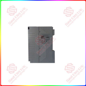
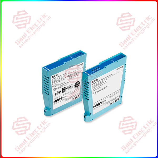
Essential details:MTL4850 modules mounted on HMP-HM64 carrier
This instruction manual describes the procedures for installing, connecting, checking and maintaining the MTL4850 HART® maintenance system, which is a simple interface between smart devices in the field and
HART instrument management software running on a PC.
The following sections are outlined here.
Section 2 describes the system and the solutions available
Section 3 covers some safety aspects.
Section 4 deals with the installation of carriers and mounting backplanes
Section 5 describes installing and configuring the modules
Section 6 provides information on fault finding, and maintenance
Section 7 introduces software for the MTL4850 System.
See the MTL web site (www.mtl-inst.com) for the full specifications of the MTL4850 system components
and accessories, and the MTL4500 Series isolators mentioned in this manual.
2 DESCRIPTION
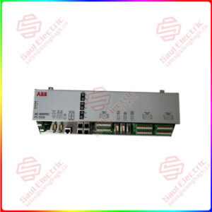
The MTL4850 HART Maintenance System enables a user to calibrate, configure and maintain an entire network of ‘smart’ field devices from a single workstation.
The key element that makes this possible is the MTL4850 module, which provides the multiplexing for the individual field devices, making each one addressable and identifiable from the workstation.
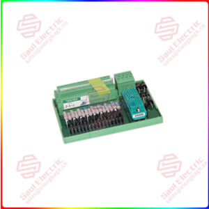
The other important element is the terminal circuit board that simplifies the interconnection of the field devices to the MTL4850 module. A range of terminal boards and backplanes has been designed to suit most general applications but custom versions can also be designed to suit individual OEMs and their applications.
MTL4850
lf you need to inquire or purchase ,please send the product models to my email or call medirectly .
sunny He
[Email] sales@xiongbagk.cn
[Mobile] 86-18059884797
[WhatsApp] 86-18059884797
[Skype] sales@saulcontrol.com
MTL4850 modules mounted on HMP-HM64 carrier
The MTL4850 module uses a plug-in style with fixing screws to provide a simple and secure installation method onto the backplane.
Up to 32 field devices can be accommodated by a MTL4850 HART multiplexer module, which is then connected via an RS485 to USB (or Ethernet) converter, to the PC running the HART maintenance software. Depending upon the management software, up to 63 of the MTL4850 modules can be connected to it, making a potential count of 2016 smart field devices on one serial link. See Figure 2.1 for a diagrammatic impression of this structure.
For intrinsically safe applications, consideration must be given to the safety parameters for each field loop. For further information, please refer to MTL or your local representative.
The MTL HART Management System can be used to control and maintain field devices that are located in a safe area or a hazardous areas.
For safe areas, HART Connection Units provide the necessary terminals to connect up to 32 field devices. These may be basic connection units, linked to a HART interface board, or they may be integrated units with an MTL4850 multiplexer onboard. Section 2.3 explains this in more detail.
Hazardous-area field devices can be handled using IS isolating interfaces conveniently mounted on a backplane with facilities for onward connection to the host. Here also there is a choice of a backplane with an onboard MTL4850 multiplexer (CPH models), or legacy backplanes that can be linked to a HART interface board that carries the MTL4850 multipexer(s).
Having the isolators mounted on a backplane dramatically reduces the amount of hand wiring required and therefore reduces the number of potential wiring errors. The hazardous-area wiring terminates on the isolating modules, not the backplane, consequently the backplanes do not need IS certification.
2.2 Generic or custom?
A range of generic connection units is available for both input and output field-device wiring. These are not designed for any particular DCS type and may be used universally.
The alternative is to choose a connection unit or backplane that integrates with the type of DCS being used on the plant. The key advantage of this method is the use of a DCS’s specific connector type, which simplifies the wiring of the connection units into the system. Various solutions are available to suit individual DCS types and a listing of the currently available connection units and backplanes is given in Appendix A