1 Year Warranty
Description
Overview
Essential details:IS220PSVOHIA Servo Control Pack GE
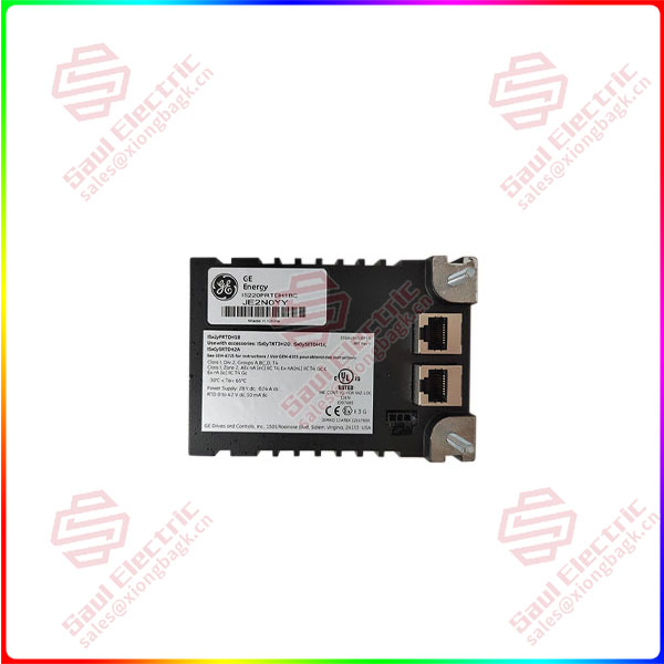
IS220PSVOH1B
Superiority products IS220PSVOHIA Servo Control Pack GE
-
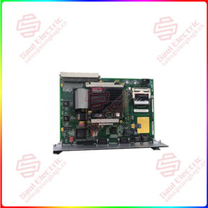
The IS220PSVOH1A is configured with the Control System Toolbox application after installation. The pack includes a processor board with input power connectors, local power supplies, and an internal sensor for temperature monitoring. The board also has flash memory and RAM onboard. This board connects to an acquisition board.
The IS220PSVOH1A can be auto-reconfigured when they are replaced. This option is enabled/disabled through the ToolboxST application through the Component Editor. The Component Editor also allows the operator to reconfigure the module manually if desired. When a terminal board is replaced, the I/O pack must be manually reconfigured.
Servo performance can be verified through stroking the actuator via manual mode, position ramping, or step current. The trend recorder will display any abnormalities in the actuator stroke. More information about this and other parts of the board, its installation and operation, as well as possible compatibility issues, can be found through manufacturer user guides and manuals.