1 Year Warranty
Description
Overview
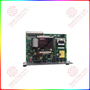
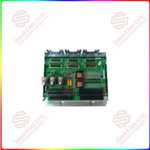
Essential details:IS200TRPGH1BDE PRIMARY TRIP TERMINAL BOARD
Part Number: IS200TRPGH1B
Manufacturer: General Electric
Series: Mark VI
Product Type: Terminal Board
Trip Solenoids: 3
Solenoid Rated Voltage/Current: 125 V dc
Solenoid Response Time: L/R time constant is 0.1 sec
Current Suppression: Metal oxide varistor
Control Relay Coil Voltage Supply: 28 V
Flame Detector Supply Voltage/Current: 335 V dc
Flame Detectors: 8
Availability: In Stock
Country of Origin: United States
Manual: GEH-6421J
FUNCTIONAL DESCRIPTION
IS200TRPGH1B is a Primary Trip Terminal Board manufactured and designed by General Electric as part of the Mark VI Series used in gas turbine control systems. The I/O controller regulates the TRPG terminal board. Three voting circuits in TRPG feature nine magnetic relays that connect to three trip solenoids, or Electrical Trip Devices (ETD). The primary and emergency sides of the interface to the ETDs are formed by the TRPG and TREG working together. For gas turbine applications, TRPG also accepts inputs from eight Geiger-Mueller flame detectors. There are two board types as follows:
- The H1A and H1B versions include three voting relays built into each trip solenoid for TMR applications.
- For simplex applications, the H2A and H2B versions have one relay per trip solenoid.
MARK VI SYSTEMS:
The VTUR board interfaces with the TRPG terminal board in Mark VI systems. TRPG is connected to the VME rack, which houses the VTUR board, through cables with molded plugs. Systems using simplex and TMR are both supported.
MARK VIe SYSTEMS:
The PTUR packs on TTURH1C control TRPG in Mark VIe systems. The D-type connectors on TTURH1C, which is connected to TRPG, accept the I/O packs as input. Systems using simplex and TMR are both supported.

IS200TRPAH1A
lf you need to inquire or purchase ,please send the product models to my email or call medirectly .
sunny He
[Email] sales@saulcontrol.com
[Mobile] 86-18059884797
[WhatsApp] 86-18059884797
[Skype] sales@saulcontrol.com
IS200TRPGH1BDE PRIMARY TRIP TERMINAL BOARD
Fig 1: TRPG Terminal Board and Cabling
INSTALLATION:
The flame detectors (if utilized) are attached directly to the second terminal block, while the three trip solenoids are wired to the first I/O terminal block. The flame detectors are linked with the power to J3, J4, and J5. J1 receives 125 V dc power for the trip solenoids, and J2 supplies power to the TREG board.
OPERATION:
The main protection solenoids are tripped by the main protection relays on TRPG, which are controlled by the I/O board. In TMR applications, a relay ladder logic two-out-of-three voting circuit is used to vote the three inputs in hardware. The I/O board keeps track of supply voltages for diagnostic purposes and tracks the current flow in its relay driver control line to determine whether to electrify or de-electrify the relay coil contact status. The diagnostics check each normally closed contact from a relay on the TRPG board to make sure it is functioning properly.
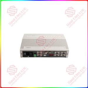
Fig 3: TRPG and Connections to Controller and Trip Solenoids
The controller transmits the primary Overspeed trip, which is subsequently transmitted to the I/O pack or board and finally to the TRPG terminal board. Together with the TREG board, which is managed by the VPRO emergency Overspeed system, TRPG functions. The TRPG/TREG combination may drive three ETDs.
DIAGNOSTICS:
The TRPG diagnostics are run by the I/O board. These include feedback from the trip solenoid relay driver and contact, the solenoid power bus, and the excitation voltage for the flame detector being too low or excessive. If any of the signals becomes abnormal, a diagnostic warning is generated (beyond limits). The terminal board’s connectors JR1, JS1, and JT1 each have their own ID device that the I/O board queries. If a discrepancy is found, a hardware incompatibility fault is generated. The terminal board serial number, board type, revision number, and plug location are all encoded on the read-only ID device chip.