Sale!

IS200ACLEH1BCB GE Mark VI (Mark 6) Speedtronic Control card

IS200ACLEH1BCB GE Mark VI (Mark 6) Speedtronic Control card

Manufacturers :GE
Model(s)  :IS200ACLEH1BCB
Additional Information :Mark VI (Mark 6) Speedtronic Control card
Estimated Shipping Size
Dimensions: 263 × 58 × 28mm
Weight:.4.3 kg
Country of Origin: United States of America


Categories: , SKU: IS200ACLEH1BCB

Description

Overview


Essential details:IS200ACLEH1BCB GE Mark VI (Mark 6) Speedtronic Control card

IS200ACLEH1BCB Technical Specifications

Model Number IS200ACLEH1BCB
Revision BCB
OEM GE Energy
Board Type Modular with Faceplate
Placement Rack Card

Product Description

The IS200ACLEH1BCB was a General Electric PCB (the Mark VI) fashioned to be used in the detailed management of steam and gas-powered turbines. The Mark VI was a part of the multi-decade long-running Speedtronic product that was crafted by GE. The Speedtronic series went through quite a few forms, opening with the Mark I which debuted in 1969. The Mark VI included things like a PC-based operator interface which was loaded with brand-exclusive software such as CIMPLICITY graphics and the GE Control System Toolbox (which was used for upkeep).

IS200EPSMG1A

lf you need to inquire or purchase ,please send the product models to my email or call medirectly .

sunny  He

[Email] sales@xiongbagk.cn

[Mobile] 86-18059884797

[WhatsApp] 86-18059884797

[Skype] sales@saulcontrol.com

IS200ACLEH1BCB GE Mark VI (Mark 6) Speedtronic Control card

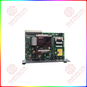
The IS200ACLEH1BCB had a thin faceplate which displayed the printed GE logo and the board ID number. Several board apparatuses were mounted to a single edge of the faceplate. This included multi-pin connectors. The board, itself, was also marked with an identification number and the manufacturing logo. It displayed the code 6BA01 along one edge of the device. Components tend to be identified by reference numbers.

The IS200ACLEH1BCB had many board connections, including a vertical male pin in the uppermost right corner, a backplane connector located on the posterior edge on the board, and a multi-pin ribbon cable connector. The ribbon connections linked to a secondary board which populated most of the center on the board. This secondary board had a few components, which included multiple pin integrated circuits and connectors. The principal board had an IDE to SATA converter that held a 128 MB memory card.