1 Year Warranty
Description
Overview
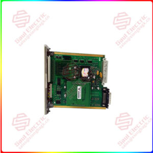
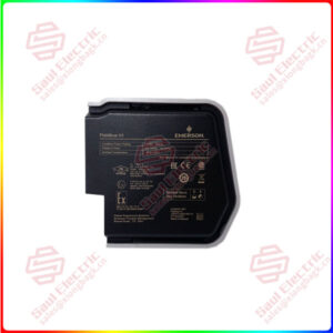
Essential details:HD22010-3 EMERSON Series charging module
The working principle block diagram of the HD22010-3 module is shown in the following figure.
Figure 1-1 Schematic diagram of HD22010-3 charging module
The HD22010-3 charging module consists of two power components: three-phase passive PFC and DC/DC. In addition to the two power sections, there is an auxiliary power supply and input output detection and protection circuit.
The front stage three-phase passive PFC circuit consists of input EMI and three-phase passive PFC, used to achieve rectification filtering of AC input and correction of input current, so that the power factor of the input circuit is greater than 0.94, in order to meet the three-phase harmonic standards in DL/T781-2001 and the relevant EMI and EMC standards in GB/T 17794.2.2-2003.
The DC/DC converter in the later stage consists of a PWM generator controlling the DC voltage output by the PFC in the previous stage, and a circuit that outputs the DC voltage through a high-frequency transformer and then rectifies and filters it to achieve stable DC voltage output required by the power operating system.
After inputting the three-phase passive PFC and before the DC/DC converter, the auxiliary power supply utilizes the DC output of the three-phase passive PFC to generate various power supplies required for the control circuit.
The input detection circuit realizes input overvoltage, undervoltage, and equality detection. The detection and protection circuit of DC/DC includes the detection of output voltage and current, the detection of radiator temperature, etc. All these signals are used for the control and protection of DC/DC.

HD22010-3
lf you need to inquire or purchase ,please send the product models to my email or call medirectly .
sunny He
[Email] sales@xiongbagk.cn
[Mobile] 86-18059884797
[WhatsApp] 86-18059884797
[Skype] sales@saulcontrol.com
HD22010-3 EMERSON Series charging module
The leftmost position of the dial switch is used to select the control mode, which is used to select whether the control mode of the module is automatic control or manual control. Dial up for automatic control, and dial down for manual control, as shown in Figure 2-4.
In automatic control mode, the output voltage, current limiting point, and switch on/off of the module are all controlled by the monitoring module, and manual intervention is not possible. If the module is connected to the closing bus to charge the battery, it should generally be set to automatic control mode.
In manual control mode, the output voltage of the module is adjusted by the manual voltage adjustment button described above. The output voltage, current limiting point, and switch of the module are not controlled by the monitoring module, but the operating parameters of the module can be reported to the monitoring module. If the module is connected to the control bus, it needs to output a single stable voltage. At this time, the module should be set to manual mode, and the output voltage of the module should be adjusted by the manual voltage regulating button. The current limiting points should be fully released, reaching 110%.
Note that the manual voltage adjustment button can make the charging module output voltage reach a maximum of 286V. Therefore, do not adjust this button arbitrarily when the system is normal. Due to differences in the number of battery sections selected by different users, for safety reasons, the output of the charging module has been set at the float charging voltage value of 234V at the factory.
② Address Identification Dial
The second digit on the left side of the dial switch is the broadcast address identification dial, used by the module to identify broadcast data packets. When dialing to the upper end, the module assumes that only packets with address 255 are broadcast packets. When dialing to the lower end, the module assumes that only packets with address 254 are broadcast packets. If equipped with an Emerson monitoring module, the dial code must be dialed to the upper end and the broadcast address must be set to 255.
③ Address setting dialing
The four digits on the right side of the dial switch are for setting the communication address of the module, which is used to set the communication address of the module.
The communication address set on the module is a binary number, with each digit dialing up representing the binary number 0 and down representing the binary number 1. The leftmost digit in the four digit address setting dial is the highest bit, and the rightmost digit is the lowest bit.
The address setting of the charging module HD22010-3 is set to 4 bits, so the address setting range of the module is 0-15, which means that the maximum number of modules connected to the same serial port of the monitoring module is 16. When the number of system modules is greater than 16, it is necessary to independently group the excess modules and communicate and connect them from another serial port of the monitoring unit.
The module address is the unique identifier used by the monitoring module to identify each charging module, and the address settings of modules in the same system cannot be the same. For the same module, the module communication address setting must be the same as the module address setting in the monitoring module, otherwise communication exceptions will occur.