1 Year Warranty
Description
Overview
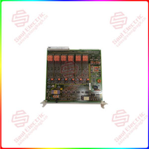
Essential details:8EI017HWD10.0100-1 B&R ACOPOS P3 servo drive
MATERIAL NUMBER:
8EI017HWD10.XXXX-1
DESCRIPTION:
The controller is divided into combinatorial logic controller and microprogram controller. The two controllers have their own advantages and disadvantages. Combinatorial logic controller design is troublesome, complex structure, once the design is completed, it can not be modified or expanded, but its speed is fast. Microprogram controller is convenient in design, simple in structure, easy to modify or expand, modify the function of a machine instruction, only need to reprogram the corresponding microprogram; To add a machine instruction, one simply adds a microprogram to the control memory, but it does so by executing a microprogram. The specific comparison is as follows: The combined logic controller, also known as the hard-wired controller, is composed of logic circuits and completely relies on hardware to achieve the function of instructions.
Electromagnetic sucker controller: The AC voltage 380V is reduced by the transformer, rectified by the rectifier to 110V DC, and then entered into the sucker by the control device. At this time, the sucker is magnetized, and the reverse voltage line is entered during demagnetization, and the controller achieves the demagnetization function.

8EI017HWD10.0100-1
lf you need to inquire or purchase ,please send the product models to my email or call medirectly .
sunny He
[Email] sales@xiongbagk.cn
[Mobile] 86-18059884797
[WhatsApp] 86-18059884797
[Skype] sales@saulcontrol.com
8EI017HWD10.0100-1 B&R ACOPOS P3 servo drive
In-depth busbar protection knowledge
The REB670 IED continues ABB’s strong track record in busbar protection, starting from analog busbar protection relays INX2/5, RADSS, REB 101/103. So far, these relays have been successfully installed for over 40 years. ABB also has more than 10 years of experience of numerical busbar protection based on REB500 and RED521. All these devices have shown an impressive track record with no false operation due to incorrect IED functioning. Today, more than 20 000 zones equipped with ABB busbar protection are in service throughout the world.
REB670 is fast and stable simultaneously – such a unique combination is essential for effective busbar protection. This IED features extremely short operate time, typically 12 ms, for most internal faults, regardless of the number of connected feeders. At the same time, it maintains complete stability for external faults, even when heavy CT saturation occurs. It also has very low CT requirements compared to other numerical differential protection devices due to its unique measuring principle, which allows the sharing of CT circuits with other protection relays and thus saves costs. The low CT requirements guarantee stability and correct operation as long as the CT is not saturated for at least two milliseconds during each power system cycle. Furthermore, the REB670 provides superior sensitivity to internal faults, thus protecting your power system objects from extensive damage and long repair times. Additionally, it effectively recognizes and operates correctly for all types of evolving faults.
Access controller: The access controller works in two modes. One is the inspection mode, and the other is the recognition mode. In the inspection mode, the controller continuously sends the query code to the card reader and receives the reply command from the card reader. This pattern continues until the card reader senses the card. When the card reader senses the card, the card reader generates a different reply to the inspection command of the controller. In this reply command, the card reader transmits the code data of the sensor card to the access controller, so that the access controller enters the recognition mode. In the recognition mode of the access controller, the access controller analyzes the code in the sensor card, compares it with the card data stored in the device, and implements subsequent actions. After receiving data, the access controller sends a command to the card reader to restore the status of the card reader. At the same time, the access controller returns to inspection mode.