1 Year Warranty
Description
Overview
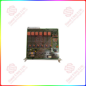
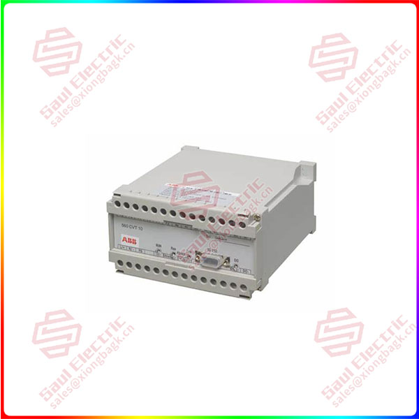
Essential details:560CVT10 Current/Voltage Transducer Interface
The Current/Voltage Transducer Interface (CT/VT interface) is used for measuring analog AC input signals from three independent phases with 3 or 4 wire connections. For each phase voltage, current and power are measured directly, and a number of other parameters derived from these in software. The results are transmitted to the RTU560.
There are several versions available:
Auxiliary Voltage (LO):
3 current-, 3 voltage inputs (In 1A)
3 current-, 3 voltage inputs (In 5A)
4 current-, 4 voltage inputs (In 1A)
4 current-, 4 voltage inputs (In 5A)
Auxiliary Voltage (HI):
4 current-, 4 voltage inputs (In 1A)
4 current-, 4 voltage inputs (In 5A)
With a powerful diagnostic tool the operator is able to fulfil below described tasks. As option the related date can be transferred over the communication link to the RTU and the control system.
x Communications over RS485 port with Modbus RTU Protocol
x User Mapping to speed up communication
x Logging of Minimum and Maximum Values
560CVT10
lf you need to inquire or purchase ,please send the product models to my email or call medirectly .
sunny He
[Email] sales@xiongbagk.cn
[Mobile] 86-18059884797
[WhatsApp] 86-18059884797
[Skype] sales@saulcontrol.com
560CVT10 Current/Voltage Transducer Interface
The fault current is measured up to 20 times nominal current. Therefore the current inputs withstand 50 times nominal current for 1 s.
The CT/VT interface is equipped with one binary output which can be used to indicate e.g. alarm for over current.
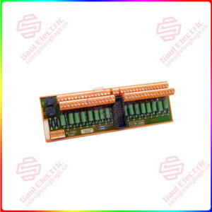
All CT/VT interfaces are mounted in the RTU cabinet. Current and voltage inputs are connected via transformer only (see Figure 1).
The CT/VT interfaces are designed for mounting on DIN rails 35 mm.
Meter Operation
The following metered parameters are available:
Instantaneous Meter Values
Measured by true RMS conversion and transmission to the RTU560 of following values:
x Phase – Neutral Voltage 1N, 2N, 3N, Average
x Phase -Phase Voltage 1-2, 2-3, 3-1, Average
x Current Phase 1, 2, 3
x Fault Current Phase 1, 2, 3, N
x Active Power, Phase 1, 2, 3, Total
x Reactive Power, Phase 1, 2, 3, Total
x Apparent Power, Phase 1, 2, 3, Total
x Power Factor, Phase 1, 2, 3, Average
x Frequency,
x Phase Rotation
x Voltage / Current Harmonic Distortion (THD,
current and voltage phase 1,2 and 3)
Derived Meter Values
x calculation of Active, Apparent and Reactive Energy accumulated values (intermediate and end of period readings, delivery and consumption)
x calculation of Ampere Hours accumulated values (intermediate and end of period readings, delivery and consumption)
x Neutral current (with 3 wire connection)