1 Year Warranty
Description
Overview
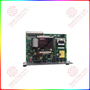
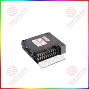
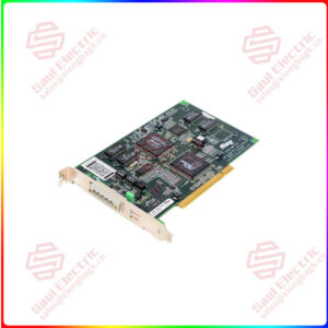
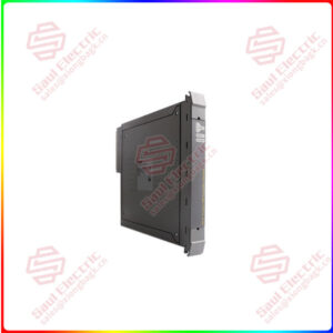
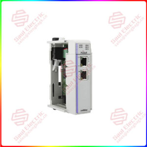
Essential details:1769-IF16C Compact High-density Analog Input Modules
The data can be configured as:
• engineering Units.
• scaled-for-PID.
• percent range.
• raw/proportional data.
Module configuration is normally done via the controller’s programming software. In addition, some controllers support configuration via the user program. In either case, the module configuration is stored in the memory of the controller. Refer to your controller’s user manual for more information.
The modules communicate to the controller through the bus interface.
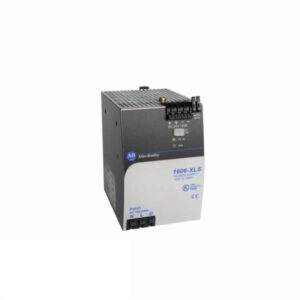
The modules also receive 5 and 24V DC power through the bus interface.
You can install as many analog modules as your power supply can support. However, the modules may not be located more than eight modules away from the system power supply.
When you cycle power, the modules perform a check of their internal circuits, memory, and basic functions. During this time, the module status OK indicator remains off. If no faults are found during power-cycle diagnostics, the module status OK indicator is turned on.
After power-cycle checks are complete, the modules wait for valid channel configuration data. If an invalid configuration is detected, the modules generate a configuration error. Once a channel is properly configured and enabled, it begins the analog-to-digital conversion process.
Each time a channel is read, the converted analog data value is tested for an over-range or under-range condition. In addition, the modules support user-configured high and low alarm condition tests for each channel. If any of these conditions are detected, unique bits are set in the channel status words.
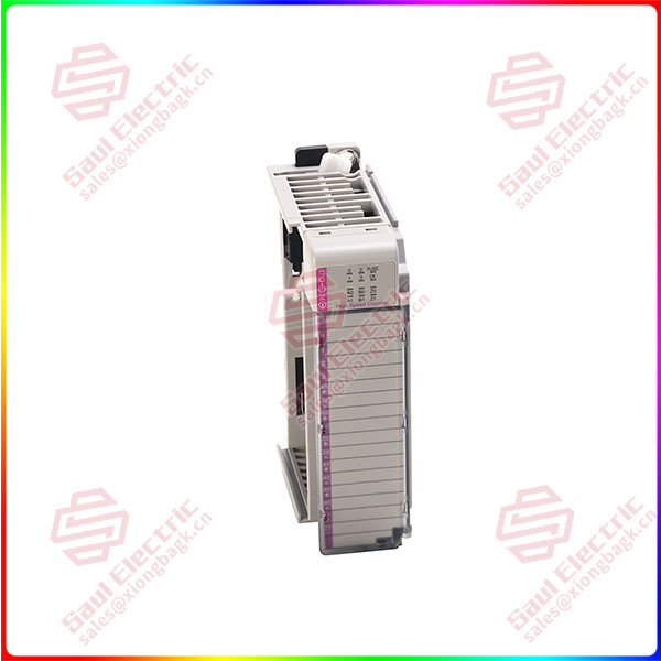
1769-IF16C
lf you need to inquire or purchase ,please send the product models to my email or call medirectly .
sunny He
[Email] sales@xiongbagk.cn
[Mobile] 86-18059884797
[WhatsApp] 86-18059884797
[Skype] sales@saulcontrol.com
1769-IF16C Compact High-density Analog Input Modules