1 Year Warranty
Description
Overview
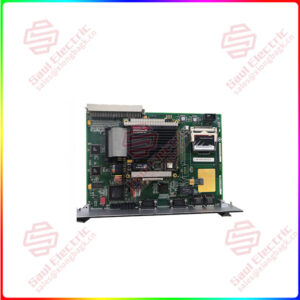
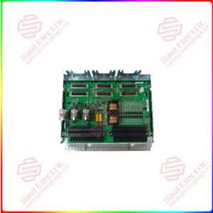
Essential details:1394C-SJT10-A SERCOS interface Multi-Axis system module
The 1394C-SJT10-A is part of the 1394 Allen-Bradley Servo Controller Series. It is an analog servo system with a traditional ±10 Volts DC interface. It is in the Series C system, which means that it has Smart Power, EMI filtering, and improved terminations. The 1394C-SJT10-A can back up as many as four axes and it can function as a velocity or torque controller. It has a Bulletin 1201 Human-Machine Interface module or HMI which allows automatic tuning and quick start-up. This servo controller weighs 23.5 pounds and measures 13.8 x 11.0 x 5.91 inches in dimensions. The 1394C-SJT10-A also has a SCANport interface. Its continuous output current is 14.73 Amps and its continuous output power is 8 / 10 kW while running on three-phase power. The 1394C-SJT10-A also has input power components such as 24 Volts AC power, a disconnect, a fuse block, a main contactor, and a 24 Volts DC power supply for motor brakes and thermal contacts. Moreover, the 1394C-SJT10-A functions in a range of 324 to 528 Volts AC at a 50 to 60 Hertz frequency, ideal for varying input voltage due to power supply fluctuation. It has an AC input current (Arms) of 13.0 Amps, a peak inrush current of 1300 Amps, line loss ride through of 20 milliseconds, and an efficiency of 99%. The 1394C-SJT10-A has a capacitance of 345 µF, an inductance of 750 µH, and its system has a 200 W continuous and 40,000 W peak internal shunt resistor. The 1394C-SJT10-A provides digital fault and diagnostic features including a current monitor, thermal overload detection, and a feedback signal monitor. Electrical noise protection and improved grounding terminations are also included.

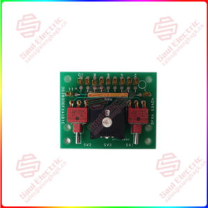
1394C-SJT05-L-RL
lf you need to inquire or purchase ,please send the product models to my email or call medirectly .
sunny He
[Email] sales@saulcontrol.com
[Mobile] 86-18059884797
[WhatsApp] 86-18059884797
[Skype] sales@saulcontrol.com
1394C-SJT10-A SERCOS interface Multi-Axis system module
The Allen-Bradley 1394C-SJT10-A is a SERCOS interface Multi-Axis system module. This module is part of the 1394 Series of motion control devices. This system module is a Series C module with enhancements including utilization of plug-in connector for input power termination; shielded bond, strain relief cable clamp; and integrated EMI filter for 24 Volts DC power and registration inputs; Smart power capability for implementing Soft-start and power monitor. This module is backward compatible with Series A and B modules. Similarly, all system module series (A, B and C) are interchangeable.
The 1394C-SJT10-A operates at an input supply voltage of 360/480 Volts AC, 3-Phase, 50/60 Hertz and input current of 13 Amperes. It delivers an output bus voltage of 530 Volts DC with an output power of 8 Kilowatts or 680 Volts DC with output power of 10 Kilowatts. It has peak power output of 28 Kilowatts, regardless of the bus voltage as well as the current output is typical for both voltages which is 15 Amperes. This system module is equipped with an optional setting. It has a built-in analog input channel that supports +/- 10 Volts DC signal.
The 1394C-SJT10-A has a capacitance of 345 µF; inductance of 750 µH and internal shunt resistor value of 200 Watts continuous, 40,000 Watts peak (two second maximum on time). Additionally, the system module has a maximum short circuit current rating of 100,000 Amperes. The 1394C-SJT10-A supports 13,000 Master/Slave electronic CAM profile points.
For installation, this system module supports panel mounting via the provided mounting holes. Minimum clearance shall be met with specific measurements of 2-inch top clearance; 0.4-inch side clearances and 3-inch clearance for depth of terminator. For bottom clearance, allow the incoming modules to maintain cable bending radius. With this, bottom clearance may vary.