1 Year Warranty
Description
Overview
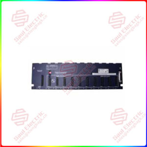
Essential details:1336-BDB-SP37C PCB Gate Driver Board Allen-Bradley
Technical Specifications for 1336-BDB-SP37C
| Brand | Allen-Bradley / Rockwell Automation |
| Series | 1336 PCB Boards |
| Part Number | 1336-BDB-SP37C |
| Description | PCB Gate Driver Board |
| Voltage | 460 Volts AC |
| Power Rating | 150 Horsepower |
| Frame | E |
The Allen-Bradley 1336-BDB-SP37C PCB (Printed Circuit Board) is a discontinued gate drive board. It is a replacement part belonging to the Allen-Bradley 1336 (Force, Impact, Plus, Plus II, and REGEN) drive component family. The 1336-BDB-SP37C Gate Drive Board provides gate control for the SCR and it is located in between the main chassis and the main control board of its host drive. The 1336-BDB-SP37C Gate Drive Board is backward-compatible, and it can serve as a suitable replacement for the 1336-BDB-SP37-A/B boards. This board is designed for the 1336 Plus II, Plus, Impact, and Force drives with 460 Volts AC input voltage ratings and total power ratings of 150 Horsepower. This drive is compatible with the E-Frame drives, and it supports every enclosure rating.
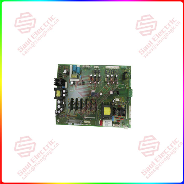
1336-BDB-SP37C
Superiority products 1336-BDB-SP37C PCB Gate Driver Board Allen-Bradley
- The 1336-BDB-SP37C PCB assembly kit contains a single spare board and installation tools. Generally, it is recommended to test the gate drive board after replacing the power module. To test the gate drive board, fuses F1 and F3 on the board are tested for open conditions by using a testing meter set in the resistance mode. To install the 1336-BDB-SP37C PCB, switch off the power and check for zero voltage at the terminal (-DC and +DC) and the absence of control voltage. Remove the main control board and detach the old gate drive board. Connect the 6 jumper connectors (J2 and J6 through J10) and the single fan connector to the new gate drive board. Re-attach the main control board and restore power to the drive. For more information on the installation process, check the online Allen-Bradley resource manuals (1336 IMPACT-6.2, 1336 FORCE-6.2, or 1336 PLUS-6.2).