Sale!

Woodward 3161 LIO  3161 EGB Governor/Actuator

Attach the speed setting linkage to the governor speed setting shaft. Typically, there will be a 50 rpm speed change for each degree of speed setting shaft rotation, however this may vary depending on the speed setting spring used in the governor. Maximum and minimum speed stops are adjusted during factory calibration of the unit.
Oil Supply
In general, the oil used in the prime mover will be satisfactory for use in the governor.
Fill the governor with clean, non-corrosive, oxidation and rust inhibiting oil that has minimum foaming or air retention qualities, and a viscosity of 100–300 SUS (Saybolt Universal Seconds) at operating temperature (typically 140–200 °F/ 60–93 °C). Fill to the line on the sight glass (approximately 2.3 US quart/2.2 L).

Categories: ,

Description

Overview


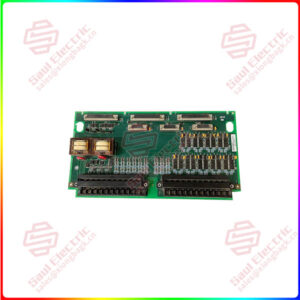
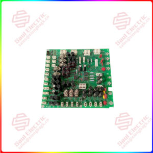
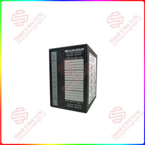
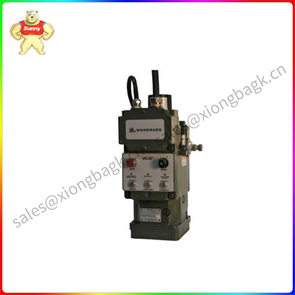
Essential details:Woodward 3161 LIO  3161 EGB Governor/Actuator

Attach the speed setting linkage to the governor speed setting shaft. Typically, there will be a 50 rpm speed change for each degree of speed setting shaft rotation, however this may vary depending on the speed setting spring used in the governor. Maximum and minimum speed stops are adjusted during factory calibration of the unit.
Oil Supply
In general, the oil used in the prime mover will be satisfactory for use in the governor.
Fill the governor with clean, non-corrosive, oxidation and rust inhibiting oil that has minimum foaming or air retention qualities, and a viscosity of 100–300 SUS (Saybolt Universal Seconds) at operating temperature (typically 140–200 °F/ 60–93 °C). Fill to the line on the sight glass (approximately 2.3 US quart/2.2 L).
After start-up, and when the oil is at operating temperature, again check the oil level and add more oil if necessary. Oil should be visible in the sight glass at all times.
Oil Viscosities
Table 2-1 shows the viscosity of oil at the different operating temperatures. The pour point (low temperature) is shown on the left and the temperature at which the performance of the oil begins to decrease is on the right side.
The governor will operate at temperatures near the pour point of the oil, but governor operation will be slow, and may be unstable. Do not operate the governor at a temperature less than the pour point of the oil.
Operating the governor at temperatures greater than the high limit (50 SUS), will decrease the stability of the governor, and may result in an inability to restart hot.
Operating the governor at a temperature greater than the point at which the performance of the oil decreases can cause governor failure.
For specific oil recommendations, see manual 25071, Oils for Hydraulic Controls.

Woodward 3161 LIO

lf you need to inquire or purchase ,please send the product models to my email or call medirectly .

sunny  He

[Email] sales@xiongbagk.cn

[Mobile] 86-18059884797

[WhatsApp] 86-18059884797

[Skype] sales@saulcontrol.com

Woodward 3161 LIO  3161 EGB Governor/Actuator

After the prime mover has started and the governor is controlling, open the needle valve (turn it CCW) until governor operation just becomes unstable. Then slowly close the needle valve (turn it CW) until the governor just becomes stable.
Allow the governor and prime mover to reach operating temperature. As the governor warms up, it may become unstable. If so, slowly close the needle valve until the governor just becomes stable. DO NOT fully close needle valve. This may cause excessive overspeed on start-up or load rejection.

Gerotor Oil Pump—The gerotor oil pump is located in the base of the governor.
The inner rotor of the pump is driven by a pin in the drive shaft, and carries the outer rotor around in mesh, pumping oil to the accumulator piston.
Accumulator—A single accumulator, consisting of a piston and spring, acts as a relief valve for the oil pump and provides a reservoir of high pressure oil for quick servo movement. Oil is pumped to the accumulator by the governor pump, with pressure increasing as the accumulator spring is compressed. When the pressure builds to the predetermined level, oil is released back to sump through relief ports in the piston wall.
Power Piston—The power piston is attached to the output shaft by a link and lever assembly. The power piston is designed with a large area on the bottom and a small area on top (differential piston). A small pressure increase on the large area of the piston will move the piston up, causing the output shaft to rotate in the “increase” direction. The piston can move down only when oil under the piston is released to sump. Oil to or from the bottom of the power piston is regulated by the ballhead pilot valve and ballhead pilot valve bushing.