1 Year Warranty
Description
Overview
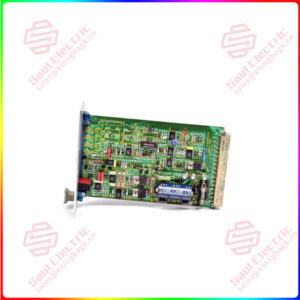
Essential details:VT-VRRA1-527 REXROTH Electrical Amplifier
▶ Diff erential input (±10 V)
▶ Four callable command value inputs (±10 V)
▶ Current input (4 … 20 mA)
▶ Inversion of the internal command value signal via 24 V input or jumper
▶ Selection of ramp time via quadrant recognition (24 V input) or ramp time call-ups (24 V inputs) with option T5
▶ Selection of the ramp time range via jumper
▶ Characteristic curve correction by means of separately adjustable step levels and maximum values
▶ Enable input
▶ “Ramp on/off ” input
▶ “Ready for operation” output signal
▶ Switchable measuring socket with option T5
▶ Reverse polarity protection for the voltage supply
▶ Power supply with DC/DC converter without raised zero point
VT2000-52-A
lf you need to inquire or purchase ,please send the product models to my email or call medirectly .
sunny He
[Email] sales@xiongbagk.cn
[Mobile] 86-18059884797
[WhatsApp] 86-18059884797
[Skype] sales@saulcontrol.com
VT-VRRA1-527 REXROTH Electrical Amplifier
Command value call-ups [4]
Four command value signals “w1” to “w4” can be called up.
The external command value voltages (command values 1 to 4) are either defined directly by the regulated
voltage outputs +10 V and –10 V or via external potentiometers. If these command value inputs are directly connected
to the regulated voltages, the command values are set at
the potentiometers “w1” to “w4”. When using external
potentiometers, the internal potentiometers will function as
attenuators or limiters.
Only one call-up can be operated at the same time. If several call-ups are operated simultaneously, call-up “1” has
the lowest priority and call-up “4” has the highest priority.
The respective active call-up is indicated via a yellow LED
on the front plate.
Command value inversion [7]
The command value created internally from the input
signals, the command value call-ups and the zero point
offset signal can be inverted by an external signal or
jumper J1. The inversion is indicated by an LED (“–1”) on
the front plate.