1 Year Warranty
Description
Overview
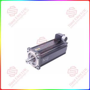
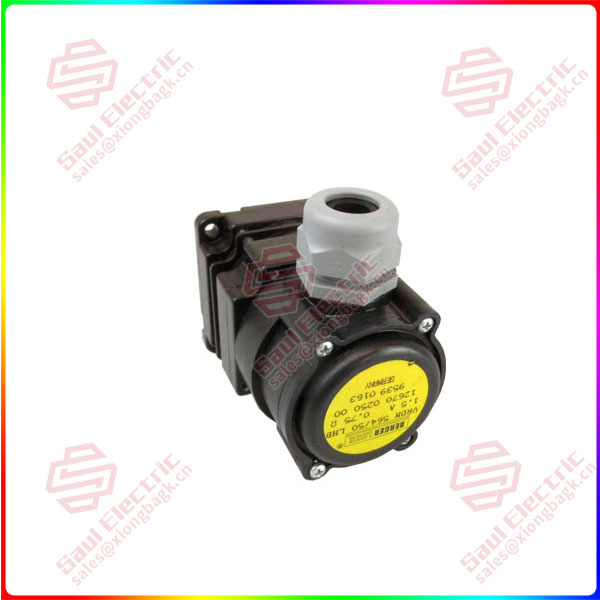
Essential details:VRDM564/50LHA Stepping motor driver BERGER LAHR
1. What is a stepper drive?
The stepper driver is a power amplifier that drives the operation of the stepper motor, which can receive the control signal sent by the controller (PLC/ MCU, etc.) and control the corresponding Angle/step of the stepper motor. The most common control signal is the pulse signal, and the stepper driver receives an effective pulse to control the stepper motor to run one step. The stepper driver with subdivision function can change the inherent step Angle of the stepper motor to achieve greater control accuracy, reduce vibration and increase output torque. In addition to the pulse signal, the stepper driver with bus communication function can also receive the bus signal to control the stepper motor to carry out the corresponding action.
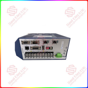
2. Wiring and setting of stepper driver
At present, there are many stepper drivers on the market, and the drivers of various manufacturers have similar interfaces, and they have terminals such as signals, power supplies, and motors. Dip switch with output current and subdivision drive Settings. This section uses LeadShine’s DM542 stepper driver as an example to introduce the wiring and Settings of the next stepper driver.
DM542 is a two-phase stepper motor driver introduced by Leisai Company. It is controlled by pulse mode and supports 8-gear current and 16-gear subdivision drive. Input voltage range: DC 20V~50V, output peak current range: 1.0~4.2A;
VRDM56450LHA
lf you need to inquire or purchase ,please send the product models to my email or call medirectly .
sunny He
[Email] sales@xiongbagk.cn
[Mobile] 86-18059884797
[WhatsApp] 86-18059884797
[Skype] sales@xiongbagk.cn
VRDM564/50LHA Stepping motor driver BERGER LAHR
2.1. Control signal terminals
The control signal terminal is connected with PLC, MCU or other controllers to receive the pulse, direction and enable control signals sent by the controller.
2.1.1 Pulse Signal
The pulse signal has two terminals: PUL+ and PUL-. PUL+” is connected to the positive pulse signal, “PUL-” is connected to the negative pulse signal; The pulse signal is measured by the voltage difference between “PUL+” and “PUL-“; Dip switch SW13 can set the effective edge of the pulse, the default (SW13=OFF) rising edge is effective;
2.1.2 Direction Signal
The directional signal has two terminals: DIR+ and DIR-. DIR+” connects the positive direction signal, “DIR-” connects the negative direction signal; The initial running direction of the stepper motor is related to the wiring of the motor winding, and any group of winding interchangeability (such as A+ and A- interchangeability) can change the initial running direction of the motor; The direction change of the motor during operation can be controlled by the direction signal. In order to ensure the reliable reversal of the stepper motor, the direction signal should be established at least 5us earlier than the pulse signal;
2.1.3 Enable signal (Enable)
The enable signal is used to enable or disable driver output and has two terminals: ENA+ and ENA-. “ENA +” is connected to enable the positive signal, “ENA-” is connected to enable the negative signal; When the “ENA+” signal is on, the driver will cut off the power supply of each phase of the stepper motor and make it in a free state, which does not respond to the pulse signal;
Note: The input voltage value of pulse signal, direction signal and enable signal can be set by sliding switch, there are two choices of DC 5V and DC 24V, the factory default DC 24V;
2.1.4 Alarm Signal (Alarm)
Driver fault signal output for connection to the PLC/ controller input channel. The factory default ALM and COM are on-state under normal circumstances, and are off state when the drive alarms; Can be set by dip switch SW12;
2.1.4 Brake signal: the brake signal input of the stepper motor;
2.1.5 COM: common end of alarm signal and lock signal;