1 Year Warranty
Description
Overview
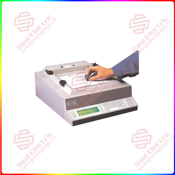
Essential details:Voltech AT3600 AT3600 Transformer Tester
The next section gives a more detailed overview of your AT3600 Tester and how to use it. It is recommended that you read this section before attempting to use your tester.
TOPICS COVERED IN THIS OVERVIEW
• The features and functionality of the AT3600 tester.
• Internal functionality.
• How the tester executes each test.
• What appears in a test program.
• How programs are created, archived and then used in actual test.
• Test fixtures.
• Typical manual and robotic test situations.
• Safety systems.
Note: This overview is intended as an introduction to each of the above topics, so that you may quickly understand what may be possible. If further details are required on any topic, they can be found in later chapters of this manual.
Measurement Circuits
The AT3600 tester contains a variety of circuits, capable of performing all the following measurements:
• Voltages from less than 1mV to greater than 7000V,
• Currents from nano-amps to amps,
• DC and harmonic analysis,
• RMS, mean-sense, wattage and VA analysis,
• Transient capture, and more.
Again, the processors select which is appropriate for each test as it is executed.
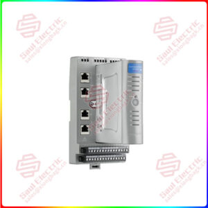
Keyboard & Display
The front-panel of the tester contains an LCD graphics panel display, three LED’s, and a membrane type alpha-numeric keyboard.
To give the greatest versatility and ease of use, the front panel ergonomics are based around four ‘soft-keys’, which are situated to the right of the display. During operation, the display provides titles for these keys, allowing them to change with the context, so that the operator is presented with only the key choices that are relevant at that point in time.
Interfaces
These include the Remote, Bar Code, Auxiliary and Server Ports located on the rear panel, and the User Port that is at the rear of the top surface.
Voltech AT3600
Zona
[Email] sales@saulcontrol.com
[Mobile] 86-18150899970
[WhatsApp] 86-18059884797
Voltech AT3600 AT3600 Transformer Tester
Because the programming of each test is done at a high level, it is not strictly necessary for you to know the details of how tests are executed within the tester.
However, for some users this subject may be of interest, therefore a brief explanation has been included here.
When the test program is loaded into the tester, each individual test is assembled into a sequence of operations involving the components in the functional block diagram shown previously. The sequence is different for each test, and in some cases, it depends on which are the preceding and following tests in the program; but in all cases, it is optimized to give the best measurement speed and accuracy.
As an example, the sequence for measuring inductance may be summarized as follows:
For other tests, the sequence may be more complicated.Notes: All the relay switching is completed before the test source is energized; thiswill ensure that there can be no arcing, and prolong the life of the relays.In contrast to some LCR bridges, the AT Series testers trim the test source togive the user programmed test conditions. This will guarantee that the sametest conditions are applied to all transformers that use the same test program.At the end of the test, the source is safely ramped down, so that the relayswitching for any subsequent test will always occur with the source removed.
The test program is simply the list of tests that you wish to apply to your transformer. Clearly individual transformers will each have their own program, but as an example, a typical program for a three winding switch-mode power supply transformer could be as follows:
The Test Program Editor supplied with your tester allows you to create such a program simply and easily without any need for software programming skills. Each test required for the program is selected from a list of ‘available tests’ by clicking with the mouse. The test details (such as the transformer terminals, test conditions, and pass / fail limits) are then entered into a form fill dialogue box.