1 Year Warranty
Description
Overview
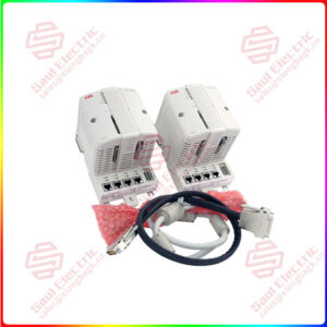
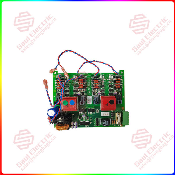
Essential details:V4559828-0001 PC Board PLC/Add-On Board
V4559828-0001 PC Board PLC/ Add-on Board is an add-on board or expansion board designed for PLC (Programmable logic Controller) systems. Such add-on boards are often used to enhance the basic functionality of a PLC or extend its interface capabilities to meet specific control needs.
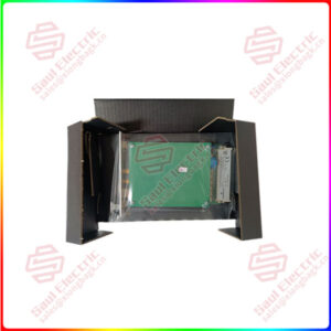
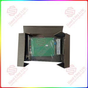
The PC board (printed circuit board) serves as the basis of the add-on board, on which various electronic components and circuits are integrated to implement specific control logic and signal processing functions. V4559828-0001 may be the model or number of the add-on board, and the specific features and specifications may vary by manufacturer and application scenario.
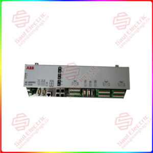
The add-on board is usually connected to the PLC through a specific interface or bus to achieve data exchange and the transfer of control instructions. They can expand the input and output points of the PLC, increase the communication interface, provide special functional modules (such as analog input/output, motion control, etc.), or achieve interconnection with other devices.
In industrial automation and control systems, PLCS and add-on boards are key components in building flexible and efficient control systems. They are widely used in various industrial fields, such as production line automation, mechanical equipment control, process control, etc.
V4561983-0100
lf you need to inquire or purchase ,please send the product models to my email or call medirectly .
sunny He
[Email] sales@xiongbagk.cn
[Mobile] 86-18059884797
[WhatsApp] 86-18059884797
[Skype] sales@saulcontrol.com
V4559828-0001 PC Board PLC/Add-On Board
Implementing a temperature sensor on an add-on board usually involves several key steps, including selecting the appropriate temperature sensor, designing the add-on board circuit, writing or configuring a PLC program to read and process temperature data, and possible calibration and debugging. Here’s a basic step-by-step guide:
1. Select a temperature sensor
First, you need to choose a temperature sensor that is suitable for your application. Common temperature sensor types include thermistors, thermocouples, RTDS (resistance temperature detectors), and digital temperature sensors (such as DS18B20). Digital temperature sensors are generally easier to interface with PLCS because they can output digital signals directly.
2. Design additional board circuit
When designing the add-on board circuit, you need to consider how to connect the temperature sensor to the add-on board and ensure that the signal can be reliably and accurately transmitted to the PLC. This may involve the use of appropriate resistors, capacitors, and operational amplifiers to condition the signal, as well as the selection of suitable connectors or interfaces to communicate with the PLC.
3. Connect the temperature sensor to the accessory board
According to the type of temperature sensor and the design of the attachment board, the temperature sensor is correctly connected to the attachment board. This may involve welding, using connectors, or other forms of connection. Make sure the connection is secure and reliable, and follow the manufacturer’s guidelines and recommendations.
4. Write or configure PLC program
Next, you need to write or configure a PLC program to read the temperature data from the attached board. This usually involves configuring the input/output mapping of the PLC so that the signal from the temperature sensor can be recognized. You may also need to write some logic to process this data, such as filtering, scaling, or alarm Settings.
5. Debugging and calibration
After hardware connection and software configuration, debugging and calibration are very important steps. Ensure that the PLC can correctly read the data of the temperature sensor and adjust it as needed. You may also need to perform a calibration to ensure that the read temperature value matches the actual temperature.
6. Integrated into the entire system
Finally, the additional board and temperature sensor are integrated into the entire PLC control system. Make sure they work in concert with other devices and components to achieve the desired control functions.