Sale!

TK-FPDXX2 Honeywell Battery Extension Module

TK-FPDXX2 Honeywell Battery Extension Module

Manufacturers :Honeywell
Model(s)  :TK-FPDXX2
Additional Information :Battery Extension Module
Estimated Shipping Size
Dimensions: 263 × 58 × 28mm
Weight:.4.3 kg
Country of Origin: United States of America


Categories: , SKU: TK-FPDXX2

Description

Overview


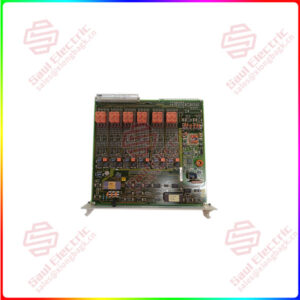
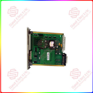
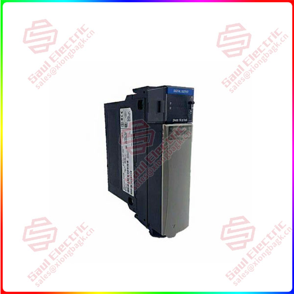
Essential details:TK-FPDXX2 Honeywell Battery Extension Module

  • Manufacturer : Honeywell
  • Product No. : TK-FPDXX2
  • Product Type : Battery Extension Module
  • Current draw @ 24vdc (amps) : 0.036
  • Current draw @ 5vdc (amps) : 0.112
  • Weight : 0.36 Kg
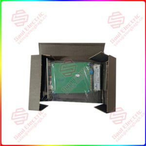
  • Shipping Weight : 2 Kg

TC-PPD011

lf you need to inquire or purchase ,please send the product models to my email or call medirectly .

sunny  He

[Email] sales@xiongbagk.cn

[Mobile] 86-18059884797

[WhatsApp] 86-18059884797

[Skype] sales@saulcontrol.com

TK-FPDXX2 Honeywell Battery Extension Module

The SR469-P5-HI-A20-E-H is a basic unit with 5 Amp phase CT secondaries.   The unit has a control power rating of 90-300 VDC, 70-265 VAC @ 48-62 Hz.   Analog outputs are 4-20 mA.   The enhanced front panel includes LED indicators, an LCD 40-character display, communication port, and keypad.

GE Multilin manuals will provide a more in-depth look at this and other SR 469 modules.  Datasheets from GE will also give you more information regarding this unit, including handling specifications and particular warnings that should be followed for a safe installation.

TK-FPDXX2 Honeywell Battery Extension Module

What is the S3 settings page entered for the SR469-P5-HI-A20-E-H GE relay?
The S3 settings page is found in the “Control System Requirements” headings and is used for entering digital inputs of characteristics. For most of the digital inputs with the SR469-P5-HI-A20-E-H motor management relay have pre-defined digital functions that can be selected on a list. The user defined digital functions are call “General Switches” A through D and can be found with the assignable inputs that are associated. These input functions need to be set to operate the relays outputs (with or with out delay), have dry contacts that are connected to the digital input terminals and respond to the status changes. To set these functions, you will need to change the names that are defaulted in the system to something you will identify very easily and have meaning behind the names. You can enter these name changes from the LCD or when ever the event reports are being reviewed. Recognize the inputs asserted logics and explain the digital inputs functions. When selecting any of the other pre-defined input functions, you can set them to trigger alarms and trips, and also when needed, energize auxiliary outputs.
What are the settings for the S5 Thermal Model and what does it contain in the settings page for this SR469-P5-HI-A20-E-H motor management relay from GE?
This SR469-P5-HI-A20-E-H Relay has a settings page for protection for the motor while the starting process is turning on, also while the motor is operating normally. These settings can be found in the S5 Thermal Model settings page, the settings for the S5 Thermal Model can be found in the manual for the SR469-P5-HI-A20-E-H Motor Management Relay. Some of the settings are standard, like the curve style selection and the assign trip relays set to “Trip”, but more specific settings should be set to the specific relay you purchased. Please refer to the manual for guidance.