1 Year Warranty
Description
Overview
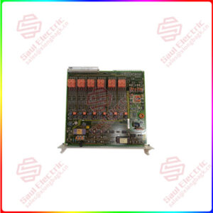
Essential details:SPAJ140 Overcurrent and earth-fault relay
The combined overcurrent and earth-fault relayis a secondary relay to be connected to thecurrent transformers of the protected objectThe three-phase overcurrent unit and the earthfault unit continuously measure the phase currents and the neutral current of the protectedobject. On detection of a fault the relay starts,trips the circuit breaker, initiates auto-reclosingprovides alarm, records fault data etc. in accord.ance with the application and the configuredrelay functions.
When the phase current exceeds the set startcurrent of the low-set stage I>, the overcurrentunit starts delivering a start signal after a preset-60 ms start time.When the set operate time atdefinite time operation or the calculated operatetime at inverse time operation elapses, the over.current unit operates. In the same way the high.set stage l>> of the overcurrent unit starts deliv.ering a start signal after a preset ~0 ms starttime,when the set start current is exceededWWhen the set operate time elapses, the overcur.rent unit operates.
When the earth-fault current exceeds the setstart current of the low-set stage lo>, the earth.fault unit starts delivering a start signal after apreset -60 ms start time.When the set operatetime at definite time operation or the calculatedoperate time at inverse time operation elapsesthe earth-fault unit operates. In the same waythe high-set stage lo>> of the earth-fault unit
starts delivering a start signal after a preset ~40ms start time,when the set start current isexceeded,When the set operate time elapses, theearth-fault unit operates.
Thelow-set stage ofthe overcurrentunitand thelow-set stage ofthe earth-fault unit may be givendefnite time or inverse defnite minimum time(IDMT) characteristic.When the IDMT char.acteristic is chosen six time/current curves areavailable. Four ofthe curves comply with the BS142 and lEC 60255 and are named “Normalinverse”,”Very inverse”,”Extremely inverseand “Long-time inverse”. The two additionalinverse time curves called the “RI-curve” andthe “RXlDG-curve” are also provided.
Byappropriate configuration ofthe output relaymatrix, the start signals of the overcurrent andearth-fault units are obtained as contact func.tions. The start signals can be used for blockingco-operating protection relays, for signallingand for initiating auto-reclosing.
The relay includes one external binary input,which is controlled by an external control voltage. The function of the control input is deter.mined by selector switches in the protectionrelay module. The control input can be used forblocking the operation of one or more protec-tion stages, for resettingalatchedoutput relayinthemanual reset mode or for enforcing a new setof relay setting parameters by remote control.
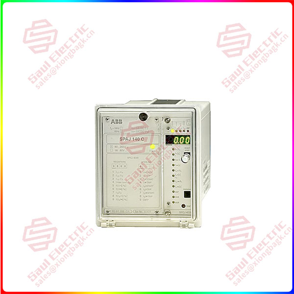
SPAJ140C-AA
lf you need to inquire or purchase ,please send the product models to my email or call medirectly .
sunny He
[Email] sales@xiongbagk.cn
[Mobile] 86-18059884797
[WhatsApp] 86-18059884797
[Skype] sales@saulcontrol.com
SPAJ140 Overcurrent and earth-fault relay
The energizing currents of the overcurrent unitare connected to terminals 1-2,4-5 and 7.8.when the rated current of the CT secondarycircuits isl,= $ A.When the rated current oftheCTsecondary circuits is I,= 1 A, terminals 1-3.4-6 and 7-9 are used. The relay can also be usedin single-phase or two-phase applications simply by leaving one or two energizing inputsunoccupied.In single-phase applications thesame energizing current can be routed throughtwo energizing inputs, which may increase thcoperating speed of the overcurrent unit, espe.cially at instantaneous operation,
The energizing current for the earth-fault unit isconnected to terminals 25-26 when the ratedcurrent I= 5 A and to terminals 25-27 whenthe rated current In= l A.
The control input 10.ll can be used in threedifferent ways, i) as control input for an externalblocking signal, ii)as the control input forunlatching the trip relay, or ilii) as the contro!input for the remote control of relay settings.The requested function is selected by means ofswitches switchgroup $GB in the main menu ofthe protection relay module.
The auxiliary supply voltage of the relay isconnected to terminals 61-62. At d.c.supplthe positive lead is connected to terminal 61The level of the voltage to be applied to theterminals depends on the type of power supplyand output relay module inserted in the relay.For further details see the description of thepower supply module. The permitted auxiliaryvoltage range of the relay is marked on the relayfront panel.
Output relay A is a heavy-duty trip relay capableofcontrolling most circuit breakers. he oper.ate signals of the different protection stages arerouted to the trip relay with switches 2,í,6 and8 of switchgroup SGRl. On delivery from thefactory all the protection stages are routed to thetrip relay. A latching of the output relay A canbe selected with switches 6 and7ofswitchgroupSGB.
selected with switches1…8 ofswitchgroupSGR2.The switch matrixes for routing operate signalsto the output relays B and C are identical.Normallyoutput relay B is used for signalling onoperation of the overcurrent unit and C forsignalling on operation of the earth-fault unit.This is also the default setting of the relay ondelivery from the factory.
The start signals of the protection stages of therelay are routed to output relay D. The signals tobe routed to output relay D are selected bymeans of switches l, 3, 5 and 7 ofswitchgroupSGR1, which is a software switchgroup found inthe main menu of the protection relay module.The start signals ofthelow-setand high-setstageoftheovercurrentunit are selected with switches1 and 3, and the start signals ofthe high-set andlow-setstage ofthe earth-faultunit with switches5 and 7.