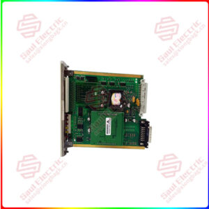
SDCS-CON-2A DCS Thyristor Power Converters for DC drive systems
Sale!
SDCS-CON-2A DCS Thyristor Power Converters for DC drive systems
The matrix below indicates all available product documentation and its corresponding order numbers on its left columns as well as all existing DC Drive systems on its top rows. System descriptions, Technical data and Operating instructions (as far as they are available for the corresponding drive) are the basic documents and will be delivered together with each drive. All other documentation has to be ordered separately.
Essential details:SDCS-CON-2A DCS Thyristor Power Converters for DC drive systems
The matrix below indicates all available product documentation and its corresponding order numbers on its left columns as well as all existing DC Drive systems on its top rows. System descriptions, Technical data and Operating instructions (as far as they are available for the corresponding drive) are the basic documents and will be delivered together with each drive. All other documentation has to be ordered separately.
General remarks
The term “DCS thyristor power converter” is a general designation for basic DC converters from ABB. This term can be found in many parts of the relevant documentation. The precise product name in accordance with the brief descriptions given below characterizes a specific unit.
Brief description of DCS 500 and DCS 500B
The DSC 500B unit range is an enhancement developed from the DCS 500 range. The difference between the two ranges lies in the version of the control board: the control board used for the DCS 500B unit range is the SDCS-CON-2 type, which is different from the SDCS-CON-1 type in several points (see the table below). Brief description of DCP 500 and DCP 500B
In the DCP 500 unit, the electronics of the DCS 500 unit have been equipped with a different power section, which changes its visual appearance, its installation dimensions and the interface between the power section and the electronics. The DCP unit is functionally compatible with the DCS unit, since the electronics (power pack, control board and options and/or control) are identical. The DCP 500B unit range is an enhancement developed from the DCP 500 range, with the difference between the two ranges lying in the control board: the control board used for the DCP 500B unit range is the SDCS-CON-2 type, which is different from the SDCSCON-1 type in several points (see the table below).
SDCS-CON-2A
lf you need to inquire or purchase ,please send the product models to my email or call medirectly .
sunny He
[Email]sales@xiongbagk.cn
[Mobile]86-18059884797
[WhatsApp] 86-18059884797
[Skype]sales@saulcontrol.com
A6500-UM Universal Measurement Card
Brief description of DCF 500B
With software release 21.232 or higher DCS 500B has a ‘3-phase field exciter mode’. A DCF 500B is a threephase field exciter based on the programmable DCS 500B software and the SDCS-CON-2 control board.
The interface boards PIN-1x/PIN-2x are modified; – an overvoltage protection unit DCF 505/506 is required.
Brief description of DCS 600
The DCS 600 converter family is based on the hardware developed for the DCS 500B type. Instead of a COM-x board, the SDCS_AMC_DC board is used. PC tools will be connected there, as well as the APC (Application controller), if the APC is used as a PLC. If a different PLC is used, separate adapter modules are needed. They must be connected to the AMC-DC board, too. The software code always begins with S15.xxx for MultiDrive or S18.xxx for Crane drives.
Brief description of DCF 600
The DCF 600 unit range is intended to be used for supplying motor fields and is based on the hardware and system configuration of the DCS 600 unit. The software is identical to the DCS 600 software. Similar to DCF 500 units the DCF 505/506 overvoltage protection unit is required. The same modification is applied to the PIN-1x/PIN-2x boards, compared to DCF 500.
Brief description of DCS 400
The DCS 400 is the smallest drive in its class. The compact design has been partly achieved by a fully integrated field exciter based on IGBT technology. A commissioning wizard – available on the control panel and the PC tool – makes start-up of the drive easy. In addition, the DCS 400 contains application macros.
The units’ power loss is made up of several different components:
• current-dependent losses PV-I
– of the thyristors
– of the fuses
– of the busbar system
• voltage-dependent losses PV-U
– snubber circuit of the thyristors
Remark:If the converter is equpped with SDCS-PIN20x use values in brackets [ ]
• almost constant losses PV-C
– unit electronics
– unit fan
– field supply
Depending on what you want to achieve by your power-loss study, you must make up your mind on the following points:
• Efficiency calculation for the drive system concerned:
For this purpose, all the power-loss components mentioned above (and additionally the losses caused, for instance, by the motor fan,
line reactor, cabling of network/power converter/motor, field supply unit and matching transformer, etc.) must be added.
• Fan losses can be estimated by 85% of the fan power consumption (see table 2.5/2).
 1 Year Warranty