1 Year Warranty
Description
Overview
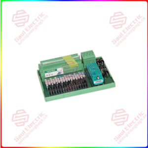
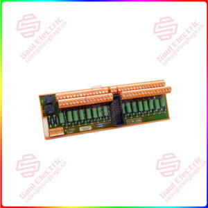
Essential details:RDCU-12C Manual RDCU Drive Control Units
Designations A…C and J1 refer to the section Mechanical installation below. The connectors (X…) are explained under Technical data further below.
Setting J1 can be further facilitated by removing the cover (see Removal and
replacement of cover below for further instructions). The jumper can also be set using long-nosed pliers or tweezers without removing the cover.
• Align the four retaining clips (A) at the top and bottom edges of the cover with the mounting rail, and carefully press the module onto the rail until the clips catch on the edges of the rail.
• Using two screws, fasten the base plate of the RDCU by the two mounting holes (B) to the mounting rail. Make sure the contact surfaces are free from dirt or grease. This is essential for the operation of the control unit since the screws provide the grounding for the unit.
Removal of unit from mounting rail
• Remove the two screws (B) holding the base plate of the unit to the mounting rail. Carefully bend the retaining clips (A) at the upper and lower edges of the cover outwards to release the unit completely from the mounting rail.
Removal and replacement of cover
• Remove all detachable (screw-type) terminal plugs from the RDCU, and disconnect any cables connected to the unit. Remove any optional modules.
If desired, the unit can be removed from the mounting rail as described above to facilitate the following steps.
• With a screwdriver or similar tool, carefully release the four cover retaining clips (C) on the right-hand side while simultaneously pulling the right-hand edge of the cover gently away from the base plate.
• Shift the cover to the left to free its left-hand edge, then pull it to detach it completely from the base and circuit board.
• Replace the cover in reverse order to the above (left-hand edge first). If the unit is already mounted onto its mounting rail, align the retaining clips (A) so that they catch on the mounting rail.
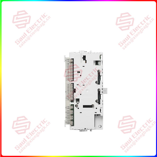
RDCU-12C
lf you need to inquire or purchase ,please send the product models to my email or call medirectly .
sunny He
[Email] sales@xiongbagk.cn
[Mobile] 86-18059884797
[WhatsApp] 86-18059884797
[Skype] sales@saulcontrol.com
RDCU-12C Manual RDCU Drive Control Units