1 Year Warranty
Description
Overview
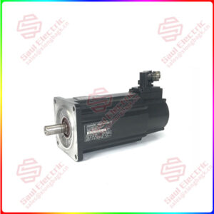
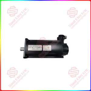
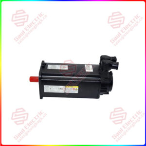
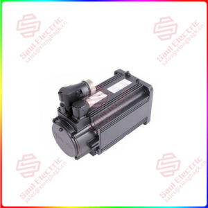
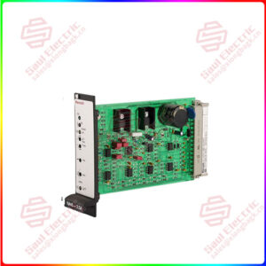
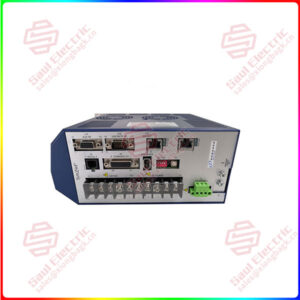
Essential details:MDX60A0075-5A3-4-00 SEW Servo driver
Safety instructions (- Sec. 1, Page 4) must be strictly observed during installati on!Use only original connection components!Observe the tightening torques of the MOVITRAC31C power terminals:Size 0->1.5 Nm(13.3 b.in)/ Size106 Nm(5.3 b.in)/Size 2 -1.5 Nm (13.3 lb.in) / Sizes 3and 4 – 3.5 Nm (31 b.in)
Observe mini mum required ventil ation spa ce of units (sufficient cooling)! Leave a minimumclearance of 100 mm (4 in) above and below the unit. No lateral clearance required.Units must be mounted vertically. Other mounting positions are not permissible!The MOVITRAC 31C is designed for operation on voltage power systems with a directlyearthed neutral point (TN and TT power systems).However, operation on vota ge power systems with a non-earthed neutral point (for examplelTpower syste ms) is also permitted. SEW recommen ds using earth-lea ka ge monitors with pulseco de mea surement in volta ge systems with non-earthed neutral points (IT systems). This prevents the earth ca pa citance of the inverter from inadvertently triagering the earth-leakage moni-tor. The EMC limit values for interferen ce emission are not specified for volta ge systems with anon-earthed neutra point (l power systems).

MDX60A0075-5A3-4-00
lf you need to inquire or purchase ,please send the product models to my email or call medirectly .
sunny He
[Email] sales@xiongbagk.cn
[Mobile] 86-18059884797
[WhatsApp] 86-18059884797
[Skype] sales@saulcontrol.com
MDX60A0075-5A3-4-00 SEW Servo driver