1 Year Warranty
Description
Overview
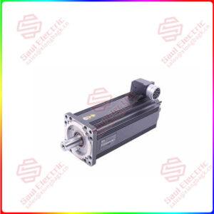
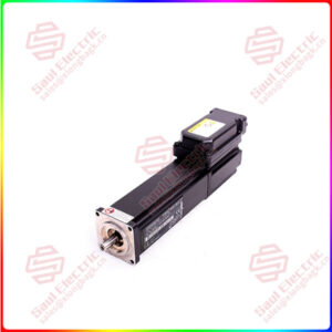
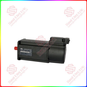
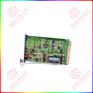
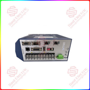
Essential details:MDS60A0150-503-4-00 DRIVE SEW
Use two closely twisted cables or a 2-core shielded power cable. Cross sectionaccording to the output rated current of the inverter.
Protect the braking resistor with a bimetallic relay (- Wiring diagram for basic unit.power section and brake). Set the trip current according to the technical data ofthe braking resistor
The connection leads to the braking resistors carry a high DC voltageapprox. 900 V) during rated operation.The surfaces of the braking resistors get very hot when the braking resistors areloaded with P. Select a suitable installation position. As a rule, braking resistorsare mounted on the switch cabinet roof.
lnstall the flat-type braking resistors together with the appropriate touch guard.
The binary inputs are electrically isolated by optocouplersThe binary outputs are short-circuit proof, although they are not interference-voltage-proof (exception: relay output DOD1). External voltage can causeirreparable damage to the binary outputs.
Only use shielded control cables.
Connect the shield by the shortest possible route and make sure it is earthedover a wide area at both ends. You can ground one end of the shield via asuppression capacitor (220 nF / 50 V) to avoid ground loops. lf using double-shieldedcables, ground the outer shield on the inverter end and the inner shield on the otherend.

MDS60A0150-503-4-00
Superiority products MDS60A0150-503-4-00 DRIVE SEW
Sizes 1 and 2 are fitted with an input filter as standard. This input filter ensures thatlimit value class A is maintained on the supply side. Use an NF…-… input filteras an option to maintain the class B limit.
The NF…-… input filter option is required for sizes 3 to 5 to maintain class A andB limits.
Install the input filter close to the inverter, but outside the minimum clearance areafor cooling.
Restrict the cable between the input filter and the inverter to the absoluteminimum length required, and never more than 400 mm (15.8 in). Unshielded.twisted cables are sufficient. Also use unshielded cables for the supply system lead.This input filter must be mounted either directly at the entry point into the switchcabinet or in the immediate vicinity of the inverter if several inverters areconnected to the same input filter. The input filter must be chosen on the basis ofthe total current of the connected inverters.No EMC limits are specified for interference emission in voltage supplysystems without an earthed star point (IT systems). The effectiveness of inputfilters in IT systems is severely limited.