1 Year Warranty
Description
Overview
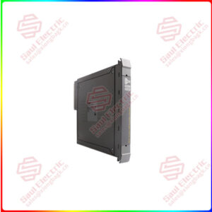
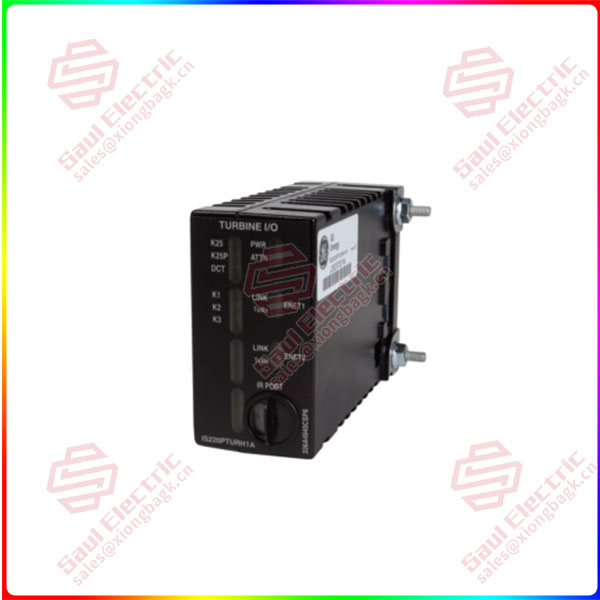
Essential details:IS220PPROS1B Emergency Turbine Protection I/O Pack
Product Description
Part No: IS220PPROS1B
Manufacturer: General Electric
Product Type: Emergency Turbine Protection I/O Pack
Series: Mark VIe
Operating temperature: -30 to 65oC
Power Supply Voltage: 24 V dc
Board Size: 14.3 cm high x 23.1 cm
Weight: 0.45 kg
Availability: In Stock
Country of Origin: USA
Manual: GEH-6721L
FUNCTIONAL DESCRIPTION:
IS220PPROS1B is an Emergency Turbine Protection I/O Pack manufactured and designed by General Electric as part of the Mark VIe Series used in GE Distributed Control Systems. A backup Overspeed protection system with a backup check for generator synchronization to a utility bus is provided by the Emergency Turbine Protection I/O pack (PPRO) and related terminal boards. They also serve as the primary control’s independent watchdog. Three triple modular redundant (TMR) PPRO I/O packs mounted to a separate simplex protection (SPRO) terminal board make up a typical protection system. Each SPRO is connected to the designated emergency trip board by a cable with DC-37 pin connections on both ends:
- TREG: Gas Turbine Emergency Trip Terminal Board.
- TREL: Large Steam Turbine Emergency Trip Terminal Board.
- TRES: Small/Medium Steam Turbine Emergency Trip Terminal Board.
- TREA: Turbine Emergency Trip Terminal Board.
IS220PPROS1B
lf you need to inquire or purchase ,please send the product models to my email or call medirectly .
sunny He
[Email] sales@saulcontrol.com
[Mobile] 86-18059884797
[WhatsApp] 86-18059884797
[Skype] sales@saulcontrol.com
IS220PPROS1B Emergency Turbine Protection I/O Pack
A single-board TMR protection system using three PPRO I/O packs is possible in a different configuration. The PPRO connects to the control modules via Ethernet for IONet communications. The primary and backup trip systems for the Mark* VIe control are integrated at the trip terminal board level. The Turbine Primary I/O pack, PTUR, which uses a primary trip board, provides primary protection (TRPG, TRPL, TRPS, TRPA). The PPRO I/O pack operates a backup trip board to provide backup protection (TREG, TREL, TRES, TREA).
- PPRO can handle three different types of speed signals, including hardware-implemented Overspeed, acceleration, deceleration, and basic Overspeed. The pack keeps an eye on the primary control’s performance and can check the primary speed to make sure everything is running normally.
- Through a broad range of feedback signals, PPRO keeps track of the status and functionality of the chosen trip board. PPRO will trip the backup trip relays on the trip board and initiate a trip on the primary control if a fault is found. The principal control action has no bearing on the pack and is completely independent of it.
COMPATIBILITY:
Direct mounting on SPRO or TREA is supported by PPROH1A. It is cable-compatible with TREG, TREL, and TRES when placed on SPRO.
SIMPLE MAIN CONTROL:
The Mark VIe trip board TRES supports simplex backup protection. The controller IONet has one PPRO network port. All Mark VIe backup trip boards, TREG, TREL, TREA, and TRES, feature TMR backup protection. In this setup, the controller IONet is connected to one port on each of the three PPRO I/O packs.
DUAL MAIN CONTROL:
The Mark VIe trip board TRES supports simplex backup protection. The R controller is connected to the network first when this setup is used. The S controller is accessible via the second network connection. Then, PPRO is in charge of overseeing the performance of both controllers. The pack trips if either controller fails, or both controllers fail, according to PPRO.
INSTALLATION:
The Mark VIe SPRO or TREA terminal board accepts the PPRO’s direct mounting. Cables with DC-37 pin connections on both ends are necessary between the SPRO board and the chosen trip terminal board when placed on an SPRO board. The following are the installation steps:
- Install the SPRO or TREA terminal board firmly. If SPRO is used, mount the chosen trip terminal board.
- If TREA is not utilized, connect a cable with DC-37 pin connections on both ends between SPRO and the chosen trip terminal board.
- Directly connect three PPRO modules to TREA or one PPRO module to each SPRO.
- PPRO’s threaded posts, which are situated on either side of the Ethernet ports, should be slid into the openings in the mounting bracket for the terminal board.
- To ensure a tight fit between the PPRO’s DC-62 pin connector and the terminal board, adjust the bracket’s position. Secure the mounting bracket firmly.
- Only one adjustment should be necessary during the lifespan of the product. Lock PPRO in place by firmly tightening the nuts on the threaded posts.
- Depending on the setup of the machine, connect either one or two Ethernet wires. The PPRO module chooses the appropriate operation over either port and is not sensitive to Ethernet connections.
- Connect the module’s power connector, which is located on its side, to power it up. The I/O module has a built-in soft-start feature that regulates current levels when used.
- To customize the module as needed, use the ToolboxST* program.
OPERATION:
The I/O pack or module function-specific acquisition board is connected to the processor board. The soft-start circuit ramps up the voltage available on the processor board when input power is applied. The processor reset is turned off and the local power supply is turned on in order. After finishing self-test routines, the processor loads application code from flash memory that is particular to the I/O pack or module type. To verify that the application code, acquisition board, and terminal board are correctly matched, the application code reads the board ID information. When there is a good match, the processor makes an effort to start Ethernet connections by asking for a network address.
The whole circuitry required to enable the I/O pack to function from one or two Ethernet inputs is contained in the processor application code. Both network pathways are constantly active when two Ethernet inputs are used. The I/O pack or module operation will not be hampered by a failure of either network, and the functioning network connection will reveal the failure. Compared to a traditional hot-backup system, where the second port is only used when the primary port fails to function, this configuration is more fault tolerant. The processor’s Ethernet ports automatically negotiate between half-duplex and full-duplex operation at speeds between 10 MB/s and 100 MB/s. Each Mark VIe Ethernet I/O pack or module shares a processing board. It has the following in it:
- A fast CPU with flash memory and RAM.
- Two connectorized, totally independent 10/100 Ethernet ports.
- A hardware reset circuit and watchdog timer.
- A temperature sensor inside.
- LEDs that display status.
- The capacity to read IDs on other boards through electronic means.
- An input power connector with a current limiter and a soft start.
- Local power supplies, with monitoring and sequencing.