1 Year Warranty
Description
Overview
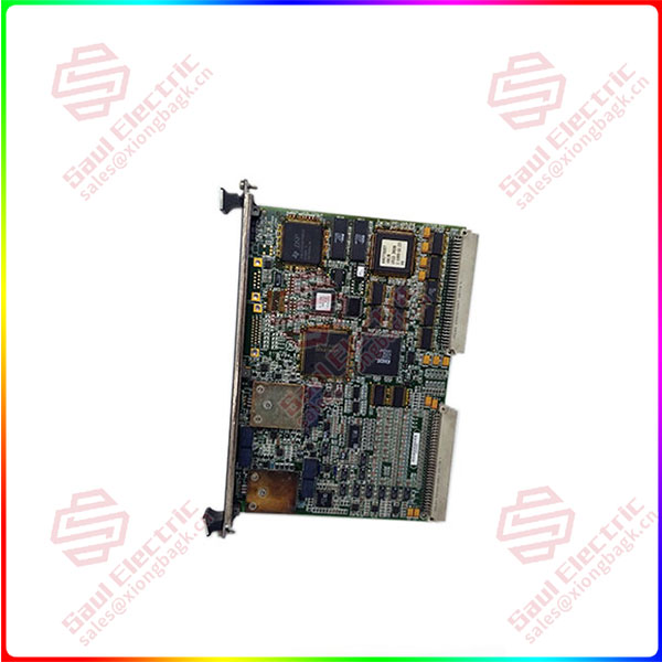
Essential details:IS200VAICH1D VME ANALOG INPUT MKVI BOARD
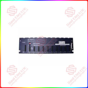
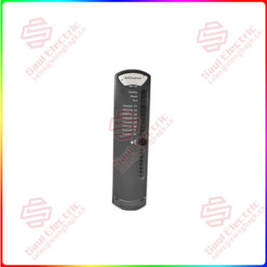
As a single-width board, the unit has a narrow front faceplate with a retaining clip located at each end. The front faceplate has three LED indicators built into its front. These will indicate updates to status, as well as information on run and fail issues.
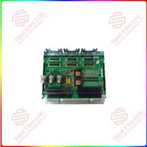
The board itself is designed with two backplane connectors spaced equally on the rear edge of the board. These connectors allow the board to communicate with the rack and other boards within it. Typically, such connectors are designed as 37-pin connectors.
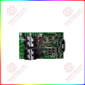
Other board components include processor chips and other integrated circuits, relays, resistors, transistors, and diodes. The components may be marked with their original manufacturer identification part number, which will allow you to use datasheets for additional information. All are marked with some sort of reference designation on the surface of the board.
Part No.: IS200VAICH1D
Manufacturer: General Electric
Country of Manufacture: United States
Product Type: Contact Input Group Isolation terminal board
Series: Mark VI
IS200VAICH1D is a Contact Input Group Isolation terminal board developed by GE. The VAIC (Analog Input/Output Control) board accepts 20 analog inputs and controls four analog outputs. Ten inputs and two outputs are available on each terminal board. The terminal board is connected to the VME rack, which houses the VAIC processing board, through cables. VAIC converts the inputs to digital values and sends them to the VCMI board, which then sends them to the controller through the VME backplane. The VAIC translates digital values to analog currents and drives them into the customer circuit via the terminal board. Both simplex and triple modular redundant (TMR) applications are supported by VAIC.
- The terminal board’s input signals are fanned out to three VME board racks R, S, and T, each containing a VAIC, when used in a TMR setup. IS200VAICH1D is a Contact Input Group Isolation terminal board developed by GE.
- The VAIC (Analog Input/Output Control) board accepts 20 analog inputs and controls four analog outputs. Ten inputs and two outputs are available on each terminal board. The terminal board is connected to the VME rack, which houses the VAIC processing board, through cables.
- VAIC converts the inputs to digital values and sends them to the VCMI board, which then sends them to the controller through the VME backplane. The VAIC translates digital values to analog currents and drives them into the customer circuit via the terminal board.
- Both simplex and triple modular redundant (TMR) applications are supported by VAIC. The terminal board’s input signals are fanned out to three VME board racks R, S, and T, each containing a VAIC, when used in a TMR setup.
IS200VAICH1D Compatibility
The VAIC board comes in two generations, each with its own terminal board. All versions before to and including VAICH1C are included in the original VAIC. This generation also includes VAICH1B. These boards can sustain up to 500 load resistance at the end of 1000 feet of #18 wire while driving 20 mA outputs. For optimal operation, this generation of board requires terminal board TBAIH1B or earlier. They are also compatible with all DTAI terminal board revisions.
Installation
To install the V-type board, follow these instructions.
- Turn the VME processor rack off.
- To seat the board’s edge connectors, slide it in and push the top and bottom levers in with your hands.
- Tighten the captive screws on the front panel’s top and bottom.
IS200VAICH1DAB
lf you need to inquire or purchase ,please send the product models to my email or call medirectly .
sunny He
[Email] sales@saulcontrol.com
[Mobile] 86-18059884797
[WhatsApp] 86-18059884797
[Skype] sales@saulcontrol.com
IS200VAICH1D VME ANALOG INPUT MKVI BOARD