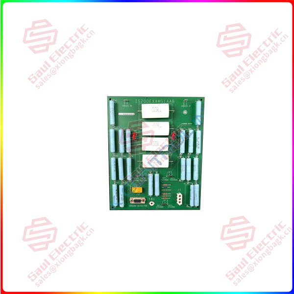
Part Number: IS200EXAMG1B
Manufacturer: General Electric
Series: EX2100
Function: Exciter Attenuation Module
Availability: In Stock
Country of Origin: United States (USA)
IS200EXAMG1B is an Exciter Attenuation Module designed by General Electric as a part of EX2100 used to control the excitation control systems. The EXAM combined with exciter ground detector module IS200 EGDM provides the ground detection systems for the EX2100 excitation control. The EXAM mounts in the high voltage interface (HBI) module that is located in the accelerated cabinet.
IS200EXAMG1B Functional Description
- It provides attenuation between the field bus and the EGDM by sensing high voltage from the bridge and scaling the voltage to a usable level. The EXAM and EGDM(s) are connected through the exciter power backplane IS200 EPBP. A single 9-pin cable connects the EXAM to the EPBP. The EGDM(s) plugs into the EPBP through a 96-pin connector. Only one EXAM is requested for simplex and triple modular redundant applications and the interconnection is the same. The EXAM does not include any test points, fuses, or LED indicators. The module includes two plug connectors, two stab-ON connectors, a ground connection terminal, and three adjustable jumpers.
- A set of three EGDMs is configured as the controller (C), Master 1 (M1), and Master 2 (M2) in TMR applications (M2). Each EGDM is automatically configured via the program pins of the EPBP’s 96-pin P2 connector. The DSPX board sends information to EGDM C about which master supplies the 50 V ac square-wave signal to the sense resistor in the EXAM. If M2 is the master, EGDM C either powers the relay in the EXAM or leaves it unpowered if M1 is the master.
- At the same time, a differential signal indicating the selected master is sent to M1 and M2. This signal activates the active master’s signal generator and selects the test command source on each EGDM (M1, M2 and C). The active master sends to the EXAM a positive or negative 50 V ac square-wave signal that is applied to one end of the sense resistor (Rx).
Connector J2 sends the square wave signal to the EXAM and receives the sense resistor signals from the EGDM. During field flashing, the square wave signal is removed.
- The field voltage (Vbus+ and Vbus) ranges from 125 V dc to 1000 V dc, and the power potential transformer (PPT) voltage ranges from 120 to 1300 V ac rms. The EXAM has two filter capacitance variations that can be selected using jumpers JP1 and JP2.
- PPT voltages below 750 V rms
- PPT voltages in excess of 750 V rms
 1 Year Warranty