1 Year Warranty
Description
Overview
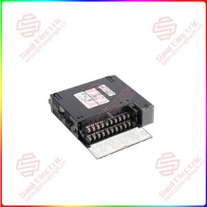
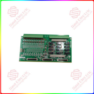
Essential details:IS200EMIOH1A Exciter Main I/O Board under EX2100 Series
Part Number: IS200EMIOH1A
Manufacturer: General Electric
Series: EX2100
Product Type: Exciter Main I/O Board
Weight: 2lbs
Availability: In Stock
Instruction Manual: GEI-100453
Country of Origin: United States of America (USA)
IS200EMIOH1A is an Exciter Main I/O Board manufactured by General Electric under EX2100 Series. It is a single-slot, double-height VME style board that is installed in the control rack. The EPCT, ECTB, EACF, and EXTB terminal boards’ I/O is handled by EMIO. PT and CT signals are included in the I/O. Contact inputs, output relay drivers, and pilot trip relay drives are all available. It also sends logic level gate pulse signals to the ESEL board, which sends them to EGPA in the power conversion cabinet via the backplane. EMIO manages inputs and outputs from a variety of I/O boards connected to the control rack.

IS200EMIOH1A
lf you need to inquire or purchase ,please send the product models to my email or call medirectly .
sunny He
[Email] sales@xiongbagk.cn
[Mobile] 86-18059884797
[WhatsApp] 86-18059884797
[Skype] sales@saulcontrol.com
IS200EMIOH1A Exciter Main I/O Board under EX2100 Series
Application Data
The Power LED is connected to the 5 V dc power supply, and the Status LED is connected to the FPGA’s IMOK output. On the board, there are no jumpers, fuses, or cable connectors. All I/O board cabling is connected to the control backplane (EBKP). Connector P1 communicates with the other control boards via the backplane, while P2 interfaces with the I/O signals via cable connectors located on the lower part of EBKP.
IS200EMIOH1A Board Replacement (Offline)
- Ensure that the exciter has been deactivated.
- Open the control cabinet door and check any electrical circuits for power before touching them.
- Remove the EMIO board from the control rack with care as follows:
- Loosen the screws near the ejector tabs at the top and bottom of the faceplate. (The screws in the faceplate are captive and should not be removed.)
- Remove the module by lifting the ejector tabs.
- Gently pull it from the rack with both hands.
- Insert the replacement EMIO board into the appropriate rack slot.
- Begin seating the board by firmly pressing the top and bottom of the faceplate with your thumbs at the same time.
- Tighten the screws at the top and bottom of the faceplate to finish seating the board in the slot. To ensure that the module is seated squarely, tighten the screws evenly.