1 Year Warranty
Description
Overview
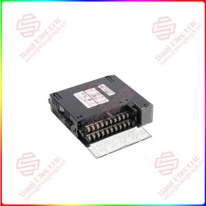
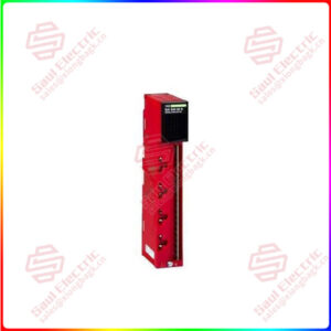
Essential details:IS200DSPXH1D Digital Signal Processor Control Board
Part No.: IS200DSPXH1D
Manufacturer: General Electric
Country of Manufacture: United States (USA)
Product Type: Digital Signal Processor Control Board (DSPX)
Series: EX2100
IS200DSPXH1D is a Digital Signal Processor Control Board developed by GE. It is the primary controller for the Innovation Series drives’ bridge, motor regulator, and gating operations. It also manages the EX2100 Excitation Control’s generator field control functions. The logic, processing, and interface functions are all provided by the board. The DSPX board is comprised of a high-performance digital signal processor (DSP), standard memory components, and an application-specific integrated circuit (ASIC) that performs custom logic functions.
Standard Hardware Features
The Digital Signal Processor (DSP) of the DSPX runs at 60 MHz. There are four externals.
During normal operation, the DSP receives interrupts:
- Stack overflow (INT0)
- A load pulse in the inner loop (INT1)
- There are two inputs that can be customized (INT2, INT3)
The DSPX board supports the following types of memory:
- DSP boot images, code execution, configurable item storage, and system history records are all stored in FLASH memory.
- RAM is used to store data and run programs.
- NVRAM stands for nonvolatile random access memory.
- Add-only memory for identifying board revisions
Both the foreground stack (from internal memory) and the background stack have overflow detection (from external SRAM). If either stack overflows, an interrupt INT0 is generated. A hard reset is generated if both stacks overflow. A configuration register is provided to disable the stack overflow reset. The DSP activates and periodically toggles a watchdog timer (toggle interval is configurable). A watchdog timer timeout will result in a hard reset. A free running timer of 24 bits is also provided and is used as a reference for certain functions.

IS200DSPXH1D
lf you need to inquire or purchase ,please send the product models to my email or call medirectly .
sunny He
[Email] sales@xiongbagk.cn
[Mobile] 86-18059884797
[WhatsApp] 86-18059884797
[Skype] sales@saulcontrol.com
IS200DSPXH1D Digital Signal Processor Control Board
As two quadrature incremental tach interfaces, five differential (HIFI) pair application inputs can be used (one with marker capability). Two 16-bit up/down counters are driven by the signals. When the inputs are at the same level, it maintains its current state; when the inputs are differentially opposite, it changes state. Each time the counter increments or decrements, a 5 MHz timer resets, and a state register records the direction of the last count. A capture register is associated with each of these counters, timers, and registers and can be configured to capture the values on the occurrence of either the inner loop load pulse or the application loop load pulse.
The five differential HIFI inputs can be used as VCO counters in the application layer or as single-channel tach interfaces. On the differentially decoded and filtered inputs, five 16-bit counters increment. The application loop load pulse stores these counter values in registers that the DSP can read. Up to ten discrete inputs can be used in addition to the five differential HIFI inputs. Each input is filtered for three system clock cycles before being read directly by the DSP into a buffer.
IS200DSPXH1D Specialized Hardware Functions
Custom logic in Field Programmable Gate Arrays (FPGAs) or ASICs with supporting circuits are used to provide specialized functions on the DSPX board. ASICs contain the majority of specialized and support functionality.
- P1 has four serial interfaces, which are as follows:
- Two 5 Mb/s ISBusTM interfaces that can be used as master or slave
- One asynchronous TTL interface for a computer-based configuration tool, with RX, TX, and TXEN/RTS data signals
- One asynchronous TTL interface to a programmer board, including data signals RX, TX, and RTS
The following functions are carried out by synchronizing load pulse signals:
- An inner loop load pulse signal records I/O values such as bridge, motor, or generator voltages and currents, as well as VCOs, tachometer counters, and discrete inputs.
It can also synchronize ISBus channels, software, and bridge gating outputs. - An application loop load pulse signal is used to capture values of other application VCOs and optionally the tachs at a sub-multiple or multiple of the inner loop load pulse.