1 Year Warranty
Description
Overview
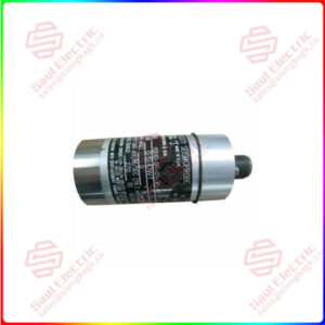
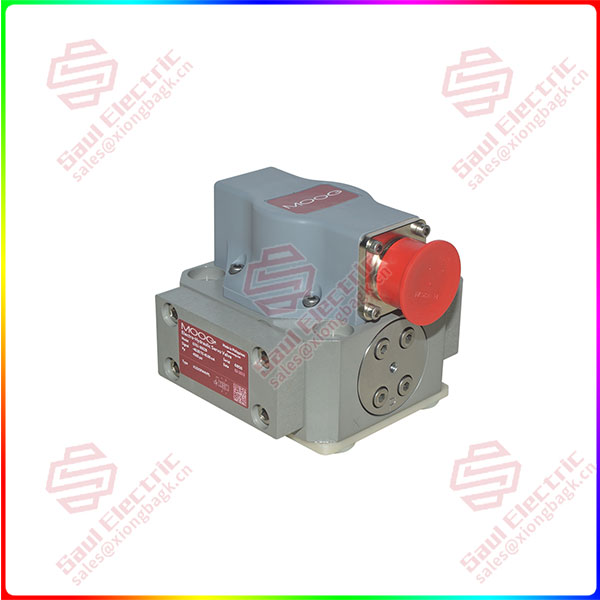
Essential details:G761-3008B G761/-761 Series Flow Control Servo Valves
The G761/-761 Series Flow Control Servo Valves are throttle valves for 3-way and preferably 4-way applications. They are a high performance, 2-stage design that covers the range of rated flows from 0.5 to 75 l/min (0.125 to 19.5 gpm) at 35 bar (500 psi) valve pressure drop per spool land.
The design is simple and rugged for dependable, long life operation. The pilot stage is comprised of a symmetrical, nozzle-flapper torque motor. The output stage includes a 4-land sliding spool, precision ground to a bushing for optimal performance. A carbide tipped feedback wire provides mechanical feedback of the spool position to the torque motor. The carbide ball on the end of the feedback wire ensures high accuracy, reliable operation and long service life. All of our Servo Valves are known for high accuracy and reliable operation even in the harshest industrial applications.
These valves are suitable for electrohydraulic position, speed, pressure or force control systems with high dynamic response requirements.
The G761/-761 Series is one of the most versatile servo valves suitable for a broad range of applications. It is the latest version of the famous 760 series that incorporates about 70 years of Moog design expertise.
The G761/-761 Series Flow Control Servo Valve consists of a polarized electrical torque motor and two stages of hydraulic power amplification. The motor armature extends into the air gaps of the magnetic flux circuit and is supported in this position by a flexure tube member. The flexure tube acts as a seal between the electromagnetic and hydraulic sections of the valve. The 2 motor coils surround the armature, one on each side of the flexure tube.
The flapper of the first stage hydraulic amplifier is rigidly attached to the midpoint of the armature. The flapper extends through the flexure tube and passes between 2 nozzles, creating two variable orifices between the nozzle tips and the flapper. The pressure controlled by the flapper and nozzle variable orifice is fed to the end areas of the second stage spool.
The second stage is a conventional four-way spool design in which output flow from the valve, at a fixed valve pressure drop, is proportional to spool displacement from the null position. A cantilever feedback spring is fixed to the flapper and engages a hole in the center of the spool.
Displacement of the spool deflects the feedback spring which creates a force on the armature/flapper assembly. Input signal induces a magnetic charge in the armature and causes a deflection of the armature and flapper. This assembly pivots about the flexure tube and increases the size of one nozzle orifice and decreases the size of the other.
The differential pressure created by this action causes spool motion. The resulting spool displacement induces a linear force in the feedback wire which opposes the original input signal torque. Spool movement continues until the feedback wire force equals the input signal force.
G761-3008B
lf you need to inquire or purchase ,please send the product models to my email or call medirectly .
sunny He
[Email] sales@xiongbagk.cn
[Mobile] 86-18059884797
[WhatsApp] 86-18059884797
[Skype] sales@saulcontrol.com
G761-3008B G761/-761 Series Flow Control Servo Valves