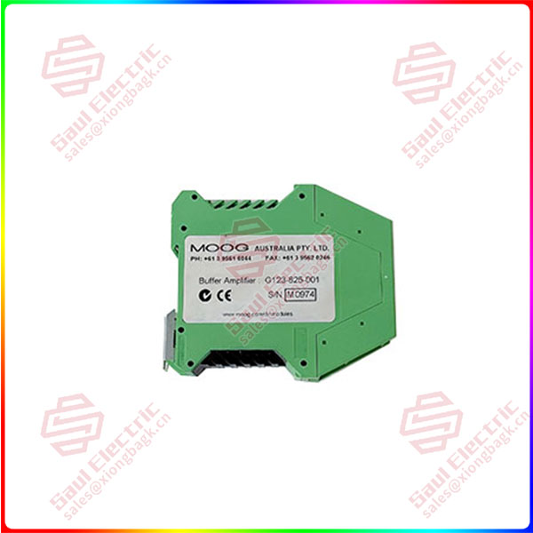
The G123-825 Buffer Amplifier is intended to interface between the output of standard signal sources, such as a PLC or servo amplifier, and a Moog servo\ proportional valve. It accepts three types of signal input and can output most of the Moog servo\proportional valve signals. It has a single pole active filter to remove noise from the input signal.
PLC ±10 V and 4-20 mA inputs:
The G123-825 interfaces between standard PLC analog output signals of ±10 V and 4-20 mA on the input side and the Moog valve on the output side. This solves the compatibility problem between these signals and the valve requirement.
Mechanical feedback (mfb) valve input:
The G123-825 interfaces between the current output of a servo amplifier, on one side, and a Moog valve on the other. This enables old mfb valves to be replaced by modern electrical feedback (efb) valves, without changing the servo amplifier.
The buffer amplifier takes the existing servo amplifier output and converts it to an efb compatible signal.
Input filter:
The G123-825 has a filter to remove noise from the input signal. The filter time constant is switch selectable. The switch selections sum, so a large variety of time constants is available.
Outputs:
The output signals are switch selectable. They are:
• 4 to 20 mA fixed. Suitable for efb valves
• 0 to ±10 V fixed. Suitable for efb valves
• 0 to ±5 to ±100 mA switch selectable. Suitable for mfb valves.
Suitable for efb valves when set to ±10 mA
The output current selector switches can have more than one selected, so the selected values sum. For example, selecting 30 and 50 mA together gives a full scale output of ±80 mA.
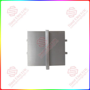
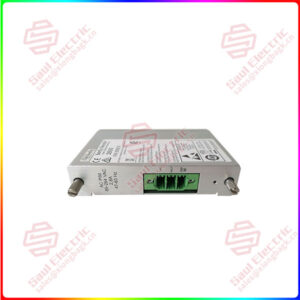
The buffer amplifier is housed in a compact DIN rail housing and requires a 24 VDC supply. Front panel test points and valve drive LEDs facilitate commissioning and trouble shooting.
G123-825-001
lf you need to inquire or purchase ,please send the product models to my email or call medirectly .
sunny He
[Email]sales@xiongbagk.cn
[Mobile]86-18059884797
[WhatsApp] 86-18059884797
[Skype]sales@saulcontrol.com
G123-825-001 G123-825 Buffer Amplifier
Scope
These application notes are a guide to applying the G123-825 Buffer Amplifier. They tell you how to install, connect and adjust the Buffer Amplifier. They do not tell you how to design the closed loop system in which it is used.
2 Description
The G123-825 Buffer Amplifier provides two types of interfaces and a filter.
2.1 PLC ±10V and 4-20mA
It interfaces between standard PLC analogue output modules, on one side, and a Moog valve, on the other. It simplifies the use of a PLC in closed loops.
The Buffer Amplifier solves the common problem of the 4-20mA or ±10V PLC output being incompatible with the valve drive requirements.
2.2 Mechanical feedback valve
It interfaces between the current output of a servoamplifier, on one side and a Moog valve, on the other. This enables old mechanical feedback (mfb) valves to be replaced by modern electrical feedback (efb) servo and proportional valves, without changing the servoamplifier. The buffer amplifier takes the existing servoamplifier output and converts it to an efb compatible signal.
2.3 Filter
The buffer amplifier provides a filter to remove noise from the input signa
3.1 Placement
A horizontal DIN rail, mounted on the vertical rear surface of an industrial steel enclosure, is the intended method of mounting. The rail release clip of the G123-825 should face down, so the front panel and terminal identifications are readable and so the internal electronics receive a cooling airflow. An important consideration for the placement of the module is electro magnetic interference (EMI) from other equipment in the enclosure. For instance, VF and AC servo drives can produce high levels of EMI. Always check the EMC compliance of other equipment before placing the G123-825 close by.
3.2 Cooling
Vents in the top and bottom sides of the G123-825 case provide cooling for the electronics inside. These vents should be left clear. It is important to ensure that equipment below does not produce hot exhaust air that heats up the G123-825.
Buffer Amplifier
G123-825
3.3 Wiring
The use of crimp “boot lace ferrules” is recommended for the screw terminals. Allow sufficient cable length so the circuit card can be withdrawn from its case with the wires still connected. This enables the switches to be changed on the circuit card while the card is still connected and operating.
An extra 100mm, for cables going outside the enclosure, as well as wires connecting to adjacent DIN rail units, is adequate.
 1 Year Warranty