1 Year Warranty
Description
Overview
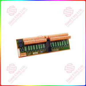
Essential details:EP-225F RSTI-EP Slice I/O Digital Output Modules
GE provides a range of RSTi-EP digital output modules with 4, 8 or 16 outputs, which are primarily used for the incorporation of decentralized actuators.
All outputs are designed for DC-13 discrete outputs according to DIN EN 60947-5-1 and IEC 61131-2 specifications. Frequencies of up to 1 kHz are possible except for relay and SSR output modules. Protection of the outputs ensures maximum system safety (Relay and SSR modules do not support short circuit protection). This consists of an automatic restart following a short-circuit.
The digital relay output module EP-2714 can control up to 4 discrete outputs, each with a maximum of 6 A. Each connector features a potential-free changeover contact. The relay coils are supplied with power from the output current path (IOUT).
The solid-state relay output module EP-2814 uses four semiconductor switches to control up to 4 discrete outputs, each with a maximum of 0.5 A at 255 V AC. The switching characteristics of the semiconductor switch have it as being closed when the voltage crosses zero and open when the current crosses zero. Each connector features a potential-free NO (Normally Open) contact.
The wiring connectors on each module are color coded for ease of wiring. Refer to the section, Field Wiring for additional information.
Each module features a type plate, which includes identification information, the key technical specifications, and a block diagram. In addition, a QR code allows for direct online access to the associated documentation. The software for reading the QR code must support inverted QR codes.
Markers are available as accessories for labelling equipment. Each I/O module can be labelled using the markers to ensure clear identification when replacing individual modules or electronic units.
A green Module Status LED indicates there is communication on the system bus.
Additionally, there are Yellow LEDs for each input to indicate when it is active. Refer to the section, LEDs for additional information.
The RSTi-EP station is usually installed on a horizontally positioned DIN rail. Installation on vertically positioned DIN rails is also possible.
Modules should to be allowed to de-energize for a minimum 10 seconds after power down, prior to starting any maintenance activity.
Refer to the RSTi-EP Slice I/O Module User Manual (GFK-2958) for additional information.
Refer to the RSTi-EP Power Supply Reference Guide, a software utility available on PME V9.00, for detailed power-feed requirements.
Module Features
Positive Logic
EP-2634 also supports Negative Logic
Spring style technology for ease of wiring
DIN rail mounted
Double-click installation for positive indication of correct installation
Up to 16 outputs
Compatible with type-1 and type-3 sensor inputs
Supports hot insertion and extraction
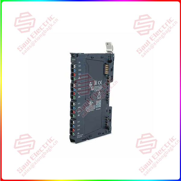
EP-225F
lf you need to inquire or purchase ,please send the product models to my email or call medirectly .
sunny He
[Email] sales@xiongbagk.cn
[Mobile] 86-18059884797
[WhatsApp] 86-18059884797
[Skype] sales@saulcontrol.com
EP-225F RSTI-EP Slice I/O Digital Output Modules