1 Year Warranty
Description
Overview
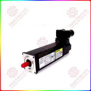
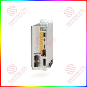
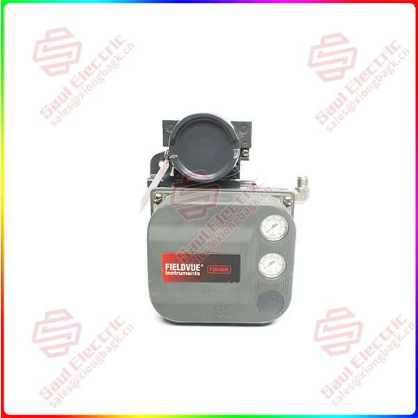
Essential details:DVC6010 GE31447X012 Digital Valve Controllers
This instruction manual includes specifications, installation, operating, and maintenance information for device revision 1, firmware revision 2−6 and device revision 2, firmware 7, 9, 10, and 11 digital valve controllers, instrument level AC, HC, AD, PD, and ODV.
This instruction manual describes using the 475 Field Communicator with device description revision 8 to setup and calibrate the instrument. You can also use Fisher ValveLink software version 7.3 or higher to setup, calibrate, and diagnose the valve and instrument. For information on using ValveLink software with the instrument refer to ValveLink software help or documentation.
Do not install, operate, or maintain a DVC6000 digital valve controller without being fully trained and qualified in valve, actuator, and accessory installation, operation, and maintenance. To avoid personal injury or property damage, it is important to carefully read, understand, and follow all of the contents of this manual, including all safety cautions and warnings. If you have any questions about these instructions, contact your Emerson Process Management sales office before proceeding.
Some of the procedures also contain the sequence of numeric keys required to display the desired Field Communicator menu. For example, to access the Setup Wizard, from the Online menu, press 1 (selects Configure) followed by a second 1 (selects Basic Setup) followed by a third 1 (selects Setup Wizard).
The key sequence in the procedure heading is shown as (1-1-1). The path required to accomplish various tasks, the sequence of steps through the Field Communicator menus, is also presented in textual
format. Menu selections are shown in italics, e.g., Calibrate. An overview of the Field Communicator menu trees are shown at the beginning of this manual.
DVC6010
lf you need to inquire or purchase ,please send the product models to my email or call medirectly .
sunny He
[Email] sales@xiongbagk.cn
[Mobile] 86-18059884797
[WhatsApp] 86-18059884797
[Skype] sales@saulcontrol.com
DVC6010 GE31447X012 Digital Valve Controllers
with the DVC6000 digital valve controller. You can obtain general information concerning software revision level, messages, tag, descriptor, and date. Diagnostic information is available to aid you when troubleshooting. Input and output configuration parameters can be set, and the digital valve controller can be calibrated. Refer to table 1-1 for details on the capabilities of each diagnostic tier.
Using the HART protocol, information from the field can be integrated into control systems or be received on a single loop basis.
DVC6000 digital valve controllers are designed to directly replace standard pneumatic and electro-pneumatic valve mounted positioners.
DVC6000 digital valve controllers (figures 1-1 and 1-2) are communicating, microprocessor-based current-to-pneumatic instruments. In addition to the normal function of converting an input current signal to a pneumatic output pressure, the DVC6000 digital valve controller, using the HART communications protocol, gives easy access to information critical to process operation. You can gain information from the principal component of the process, the control valve itself, using the Field Communicator at the valve, or at a field junction box, or by using a personal computer or operator’s console within the control room.
Using a personal computer and ValveLink software or AMS Suite: Intelligent Device Manager, or a Field Communicator, you can perform several operations