Sale!

DS200VPBLG1A GE VME Backplane Board

DS200VPBLG1A GE VME Backplane Board

Manufacturers :GE
Model(s)  :DS200VPBLG1A
Additional Information :VME Backplane Board
Estimated Shipping Size
Dimensions: 263 × 58 × 28mm
Weight:.4.3 kg
Country of Origin: United States of America


Categories: , SKU: DS200DSPCH1A-1-1

Description

Overview


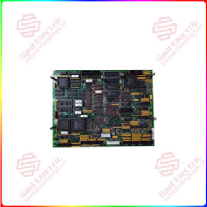
Essential details:DS200VPBLG1A GE VME Backplane Board

DS200VPBLG1A Technical Specifications

Part / Model Number DS200VPBLG1A
Common Revisions DS200VPBLG1AEE, DS200VPBLG1AFF
Functional Acronym/Abbreviation VPBL
Stock Level In Stock
Board Description VME Backplane Board
Made In Manufactured in the USA
Part Specific Manual GEI-100227
Weight 1lbs 7oz
Number of Power Bugs Ten Power Bugs
Exciter Connection 34-Pin Ribbon Connector
Section J2 Supports DSPC Board, IO Extenders, Up to Three FCGD Boards
Quantity of Testpoints Sixty Spring-Loop

Frequently Asked Questions about DS200VPBLG1A

What is a DS200VPBLG1A?

DS200VPBLG1A is a GE VME Backplane Board used in Load Commutator Inverter Control Systems along with a 13 slot chassis.

How is the backplane of the DS200VPBLG1A used?

The backplane is used for the J2 and J3 sections of the equipment’s card cage.

DS200VPBLG1A

lf you need to inquire or purchase ,please send the product models to my email or call medirectly .

sunny  He

[Email] sales@xiongbagk.cn

[Mobile] 86-18059884797

[WhatsApp] 86-18059884797

[Skype] sales@saulcontrol.com

DS200VPBLG1A GE VME Backplane Board

What is the purpose of the J2 and J3 sections on the DS200VPBLG1A model?

The J2 section on the DS200VPBLG1A board is used to support several boards, those being a DSPC board, up to three Gate Distribution and Status Boards, an I/O extender, and one exciter board with two spare slots available. The J3 section is typically used for external connections that are not on the board fronts due to space or other restrictions.

What are the tachometer settings for this board?

There are two tachometer settings within the DS200VPBLG1A board those being a twelve-pin terminal block, and jumpers that are used to configure the tachometer settings. There are ten nomenclatures for the terminal block connectors with individual descriptions, some of them are E0V2 which is tach power supply V1 – (common node choke), and E1V1 which is tach power supply V1 + (common mode choke).

What is the best way to remove the VPBL board so it can be replaced?

Firstly power should be turned off to as not to potentially warrant a shock. If the attached ribbon cables do not have pull tabs gently grasp the cable connector and pull the cable connector loose, if the ribbon cables have pull tabs carefully pull the tab. Remove all of the screws and then carefully remove the VPBL by keeping the board level.

How many test points are there on the DS200VPBLG1A board?

There are sixty spring-loop test points that are used to provide access to the digital and analog signals generated by the three phases of AC on the input power as well as the positive and negative DC outputs. Test points 55 and 62 through 118 are assigned to pins in the J2 connectors and are for factory usage only.