1 Year Warranty
Description
Overview
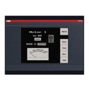
Essential details:BE3-25A Auto-Synchronizer provides
Description.The Basler BE3-25A Auto-Synchronizer provides automaticGeneralsynchronization of an oncoming generator with a bus or another generator. The Synchronizersupplies correction signals to the oncoming generator to match it to the bus or to another generatoifor frequency, phase angle, and voltage before being closed into the circuit. Options allow for deadbus closing and a variety of output configurations for frequency/phase matching and voltagematching. Construction consists of a case enclosed circuit board with extemal terminal connections.A TEST/OPERATE switch, LED SYNC and POWER indicators and all operational adjustments arelocated on the front panel or are accessible through access holes in the front panel.
b. Basic Unit Description.(1)The basic BE3-25A Auto-Synchronizer monitors both the oncoming generator and busvoltages then permits synchronizing the generator to an energized station bus or to another genera-tor when the following predetermined conditions are satisfied:
(a) The frequency of the oncoming generator and the bus are matched to within ±0.1 HertzThis corresponds to a slip frequency of +0.1 Hertz or less.
(b)The phase angle between the oncoming generator voltage and the bus voltage is lessthan or equal to the allowable limit determined by the front panel setting. This limit isestablished by the position of the front paneI BREAKER CLOSING ANGLE switch withsettings of +5°,+10°,+15°, and +20°
(c) The diference between the generator and bus voltage is less than the seledted voltagedifference setting which is continuously adjustable over the range of +5% to +15% of thebus voltage.
(2)When a jumper is connected across the 0.75 Second Time Delay terminals of the Synchro-nizer (terminals D1 and D2), the generator will be synchronized only when the generator outputvoltage is within the selected voltage difference setting and the measured phase angle and differ-.ence (slip) frequency are less than the following:

BE3-25A
sunny He
[Email] sales@xiongbagk.cn
[Mobile] 86-18059884797
[WhatsApp] 86-18059884797
[Skype] sales@saulcontrol.com
BE3-25A Auto-Synchronizer provides
Product Description
(4)Upon a loss of power (power input falls below 85 Vac for 50 and 60 Herz systems) orremoval of either the bus or generator sensing input voltage, the Synchronizer will immediatelyremove all output correction signals to the governor or voltage regulator
(5)A built-in “operational test” mode can be used to verify Synchronizer operation whenconnected to the generator. The Sync Output Relay is inhibited from operating when theTEST/OPERATE switch is set to the TEST position. A red LED (SYNC) on the front panel williluminate whenever the freguency, phase angle, and voltage are all within the contact closureparameters.
c.Frequency/Phase Angle Matching System.
(1)The freguency/phase angle matching options in the Synchronizer provide correction signalsto the generator governor control Two types of frequency/phase angle matching are available:
(a)”Bipolar” governor correction signals (summing point)for use with most commonelectronic type govemor controls manufactured by AMBAC International, Barber Coleman, andWoodward. Summing point frequency correction signals are output at maximum until the generatorfrequency is corrected to within +3 Hertz of the station bus frequency. Once the +3 Hertz limit isattained, the output signals become proportional to the amount of the diference frequency (i…: theoutput for a 3 Hertz difference is larger than the output for a 1 Hertz difference).
(b)A “raise/lower” output contact signal for use with hydraulic type govemors and motoroperated controls. Contact type correction signals are output as a contact closure. When the phaseangle is 0° or within the front panel setting for acceptable phase conditions, the contacts open andremain open. At any phase angle greater than the front panel setting, the contacts are closed.