1 Year Warranty
Description
Overview
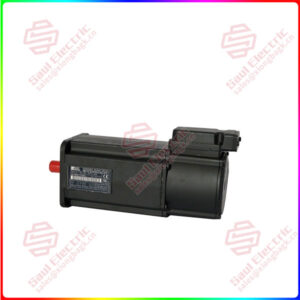
Essential details:A06B-6117-H304 FANUC Encoder module
1 Encoder classification
1.1 Classification by monitoring principle
1.1.1 Photoelectric encoder
The photoelectric encoder is a sensor that converts the mechanical geometric displacement on the output shaft into a pulse or a digital quantity by photoelectric conversion. This is currently the most used sensor, photoelectric encoder is composed of light source, optical code disk and photosensitive elements.
The grating disk is a certain diameter of the circular plate on the opening of a number of equal rectangular holes. Because the optical code disc is coaxial with the motor, when the motor is rotating, the grating disc rotates at the same speed as the motor, and the detection device composed of electronic components such as light-emitting diodes detects and outputs several pulse signals, and the current motor speed can be reflected by calculating the number of pulses output by the photoelectric encoder per second.
In addition, in order to determine the direction of rotation, the code disk can also provide two pulse signals with a phase difference of 90°.
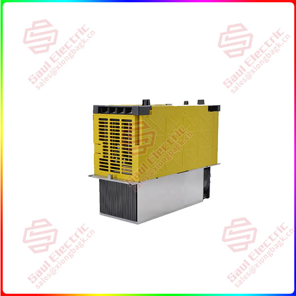
A06B-6117-H304
lf you need to inquire or purchase ,please send the product models to my email or call medirectly .
sunny He
[Email] sales@xiongbagk.cn
[Mobile] 86-18059884797
[WhatsApp] 86-18059884797
[Skype] sales@saulcontrol.com
A06B-6117-H304 FANUC Encoder module
1.2 Classification by output signal
1.2.1 Incremental encoder
Incremental encoder is to change the displacement information of the device into a continuous pulse signal, and the number of pulses indicates the size of the displacement. Its characteristics are as follows:
The signal is only output when the device is in motion.
Generally, two sets of signals of channel A and channel B are output, and there is a phase difference of 90° (1/4 cycle), and the speed and direction of the device can be calculated by collecting these two sets of signals at the same time.
In the figure below, the signal period of channel A and channel B is the same, and the phase difference is 1/4 cycle, combined with the signal value of the two phases:
When phase B and phase A both read A high level (1 1), then B reads a high level, and A reads a low level (10 0), it turns clockwise
When phase B and phase A are both read low (0 0), then B reads high, and A reads low (10 0), it is turned counterclockwise
In addition to channels A and B, an additional channel Z signal is set to indicate the specific reference position of the encoder
As shown in the figure below, the Z-axis signal will output a pulse only after the sensor turns around. When the Z-axis is output, the absolute position of the code disk can be calculated by clearing the count of the AB channel to zero.
Incremental encoders only output the position change and direction of motion of the device, and do not output the absolute position of the device.