1 Year Warranty
Description
Overview
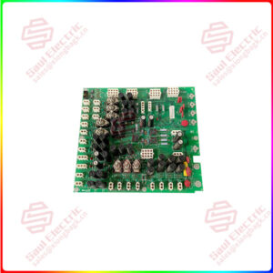
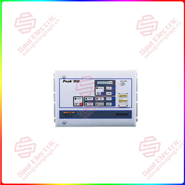
Essential details:9905-463 Load Sharing and Speed Control
These controls are available for forward- or reverse-acting applications, and for use with either single or tandem actuators. Models for three different actuator current ranges are available, as well as a high-voltage model (90 to 150 Vdc or 88 to 132 Vac, 45 to 440 Hz), and a low-voltage model (20 to 40 Vdc). The high voltage model is identified as such on the front; the low voltage model is not.
In reverse-acting systems, the actuator calls for more fuel when the actuator voltage decreases. Complete loss of voltage to the actuator will drive the actuator to full fuel. This allows a backup mechanical ballhead governor to take control rather than shut down the prime mover as would a direct-acting system.
An optional deceleration ramp is also offered. When this option is present, the time to ramp from rated speed to idle speed is approximately 20 seconds. If this option is not present, this happens instantly.
Tables 1-1 and 1-2 show part numbers and features of all 9905/9907 series 2301A load sharing and speed controls.
This product is intended for installation in a “closed electrical operating
area” or in a closed industrial control cabinet. Consider these requirements
when selecting the mounting location:
Adequate ventilation for cooling
Space for servicing and repair
Protection from direct exposure to water or to a condensation-prone environment
Protection from high-voltage or high-current devices, or devices which produce electromagnetic interference
Avoidance of vibration
Selection of a location that will provide an operating temperature range of –40 to +70 °C (–40 to +158 °F)
The control must NOT be mounted on the engine.
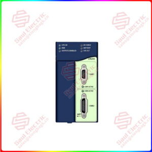
9905-864
lf you need to inquire or purchase ,please send the product models to my email or call medirectly .
sunny He
[Email] sales@xiongbagk.cn
[Mobile] 86-18059884797
[WhatsApp] 86-18059884797
[Skype] sales@saulcontrol.com
9905-463 Load Sharing and Speed Control
All shielded cable must be twisted conductor pairs. Do not attempt to tin (solder) the braided shield. All signal lines should be shielded to prevent picking up stray signals from adjacent equipment. Connect the shields to the control terminals as shown in Figure 2-1 and in the plant wiring diagram (Figure 1-2). Wire exposed beyond the shield should be as short as possible, not exceeding 50 mm (2 inches). The other end of the shields must be left open and insulated from any other conductor. Do not run shielded signal wires with other wires carrying large currents. See Woodward application note 50532, EMI Control for Electronic
Governing Systems, for more information.
Where shielded cable is required, cut the cable to the desired length and prepare the cable as instructed below and shown in Figure 2-1.
- Strip outer insulation from BOTH ENDS, exposing the braided or spiral wrapped shield. DO NOT CUT THE SHIELD.
- Using a sharp, pointed tool, carefully spread the strands of the shield.
- Pull inner conductor(s) out of the shield. If shield is the braided type, twist to prevent fraying.
- Remove 6 mm (1/4 inch) of insulation from the inner conductor(s).
- Connect wiring and shield as shown.
In installations with severe electromagnetic interference (EMI), shielded wire run in conduit, double shielded wire, or other precautions may be required. Contact Woodward for more information.