1 Year Warranty
Description
Overview
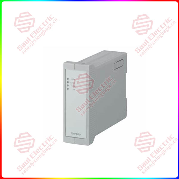
Essential details:520PSD01 RTU520 Power supply
The power supply unit 520PSD01 is used to generate the necessary power for the RTU520 system. The 520PSD01 is connected directly with the 520CMD01 via connector X1 (see Figure 1and Figure 2). The RTU520 system could only be supplied via the 520CMD01 board, other boards aren’t provided.
The input voltage is not galvanic isolated against the output voltages.
Connections
The supply voltage for the power supply 520PSD01 is 24 VDC. The connector X3 consists of a 3 pole pluggable screw-terminal 5.08mm (see Table 1 and Figure 1). The maximum input power is 24W.
Functional Earth
To obtain higher EMC protection it is important to make a connection as short as possible to a system earth (may be DIN-rail or mounting plate). An common multi-core wire can be used and should not exceed a length of 100 cm (39 inch). The third pin of the 3 pole DC-In connector is the functional earth-pin (see Table 1 and Figure 1).
520CMD01
lf you need to inquire or purchase ,please send the product models to my email or call medirectly .
sunny He
[Email] sales@saulcontrol.com
[Mobile] 86-18059884797
[WhatsApp] 86-18059884797
[Skype] sales@saulcontrol.com
520PSD01 RTU520 Power supply
The power supply unit 520PSD01 supplies a total output power of 20 W. This can be used for:
• +24VDC, max. 0.2A
• +15 VDC, max. 0.2 A
• -15 VDC, max. 0.2 A
• +5 VDC, max. 1.8 A
A label with some information about the output power could be found on the left side of the housing (see Figure 1).
Signaling
The power supply unit 520PSD01 indicates operational states by light emitting diodes on the front plate (see Figure 1).
• 24 VDC
• +15 VDC
• -15 VDC
• 5 VDC
The 24V LED is in OFF state as long as the IO-Bus not runs. The 24V LED signalize the internal 24V to the IO boards.