1 Year Warranty
Description
Overview
Essential details:469-P1-HI-A1-E GE 469 Series for the GE Generator Management Relays
489-P5-HI-A20-T-H Technical Specifications
| 4-20 mA Max. Load | 1.2 kΩ |
| Analog Current Inputs Conversion Range | 0-20 mA |
| High Voltage Terminals (E,F, G, H) | #8 ring lug, 10 AWG Wire Standard |
| High-Set Phase Overcurrent Timing Accuracy | ±50 ms at 50/60 Hz or ±0.5% total time |
| Overcurrent Alarm Pickup Accuracy | As Per Phase Current Inputs |
| Phase Distance Reach Accuracy | ±5% |
| Pulse Output Parameters | + kwh, +kvarh, –kvarh |
| RTD Inputs Temperature Range | –50 to 250°C (-58 to 482°F) |
| Volts per Hertz Elements | Alarm and Trip |
Product Description
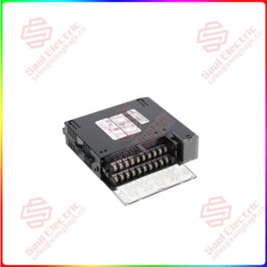
489-P5-HI-A20-T-H is a generator management relay that is manufactured by GE Multilin for the 489 series. This relay has 5 A phase CT secondaries. The HI control power is 90-300 VDC and 70265 VAC at 48-62 Hz. The analog outputs on this relay are 4 to 20 mA. This relay has an enhanced display with a larger LCD and Ethernet. A harsh environment conformal coating protects this unit from chemicals.
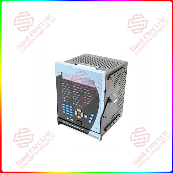
489-P5-HI-A20-T-H
lf you need to inquire or purchase ,please send the product models to my email or call medirectly .
sunny He
[Email] sales@saulcontrol.com
[Mobile] 86-18059884797
[WhatsApp] 86-18059884797
[Skype] sales@saulcontrol.com
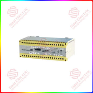
469-P1-HI-A1-E GE 469 Series for the GE Generator Management Relays
For the analog current inputs on the relay: The input impedance is 226 Ω ±10%. The conversion range is 0 to 20 mA. The accuracy is ±1% of full scale. These are passive inputs. The analog input supply is a maximum of +24 VDC at 100 mA. The sampling interval is 50 ms. The analog inputs frequency tracking is 6 V minimum and 10 Hz/second. For the digital inputs on the relay: There are 9 opto-isolated inputs. The external switch is dry contact less than 400 Ω, or open collector NPN transistor from sensor. The 489 sensor supply is 24 VDC at 20 mA maximum. For the ground current input on the relay: The CT primary is 10 to 10000 A, and the CT secondary is 1 A / 5 A. The conversion range is 0.02 to 20 × CT for 1A/5A CTs. For the neutral voltage input, the VT ratio is 1.00 to 240.00:1 in steps of 0.01. The VT secondary is 100 VAC at full scale. The conversion range is 0.005 to 1.00 (multiplied by the full scale). The maximum continuous neutral voltage input is 280 VAC.
Frequently Asked Questions about 489-P5-HI-A20-T-H
What does the P5 mean in the part number 489-P5-HI-A20-T-H for the GE Generator Management Relay?
How do you use plug and play for EnerVista Viewpoint for the GE generator management relay for the part number 489-P5-HI-A20-T-H?
How to place the GE generator management 489-P5-HI-A20-T-H relay in service?
How to set software to view as a phasor diagram with the GE generator management relay 489-P5-HI-A20-T-H?