1 Year Warranty
Description
Overview
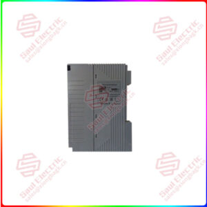
Essential details:3AFE61320954P0001 Frequency converter controller ABB
Resistors are ubiquitous and versatile. We can use them to turn tiny currents on and off
(the principle behind computer memory) and convert small currents into larger ones (the work of amplifiers).
But they don’t work as well when dealing with higher currents, and there’s also the drawback that once you remove the switching current,
they shut off completely, which means that the alarm devices that you want the circuit to trigger the ice to stay on indefinitely aren’t very useful.
For these situations, the thyristor comes in handy.
I. What is a thyristor?
A thyristor is a one-way semiconductor device made of silicon. Basically, a thyristor (SCR) is a three-terminal,
four-layer semiconductor device consisting of alternating P-type and N-type materials.
The thyristor has three pn junctions J 1, J 2 and J 3. The figure below shows a thyristor with a pnpn layer.
The thyristor has A terminal anode (A), cathode (K), and grid G), and the grid terminal (G) is connected to a p layer near the cathode (K) terminal.

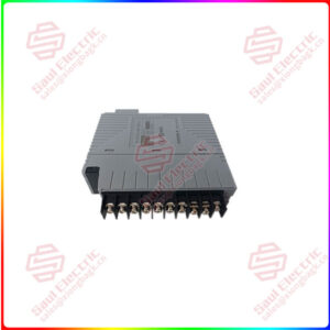
3AFE61320946P0001
Sales Manager: Manager He
E-mail number: sales@saulcontrol.com
skypel wechat: +86-18059884797
Mobile phonelwechat: +86-18059884797
QQ:3095989363
Thyristor structure drawing
Thyristor circuit symbol
Two, the thyristor is like two transistors
Four layers of transistors work like two transistors, they are connected together (as shown below),
the output of one forms the input of the other, and the gate acts as a kind of “starting motor” to activate them.
A single thyristor (SCR) is a combination of a pnp transistor (Q 1) and an npn transistor (Q 2). Here,
Q1’s emitter is the anode terminal of the SCR, and Q2’s emitter is its cathode. In addition,
the base of Q1 is connected to Q2’s collector, the collector of Q1 is connected to Q’s base, and the gate terminal of the thyristor is also connected to Q2’s base.
Thyristor structure drawing
Three, three states of thyristor
So how does a thyristor work? We can put it in one of three possible states,
in which it is either completely off or fully on, meaning that it is essentially a binary digital device.
1. Thyristor forward blocking mode
Usually, the thyristor is turned off when no current flows into the grid: no current can flow from the anode to the cathode.
Here you can think of the thyristor as two diodes connected together, with both the upper and lower diodes forward-biased.
However, this means that the junction at the center is reverse biased, so the current cannot flow from the top all the way to the bottom.
This state is called forward blocking. Although it is similar to the forward bias in conventional diodes, no current flows.
Here, positive bias is applied to the thyristor by connecting the positive terminal (A) to the positive terminal of the battery
and the negative terminal (K) to the negative terminal of the battery, as shown below. In this case,
junction J 1 and J 3 get a forward bias, while junction J 2 gets a reverse bias.
Here, electric current cannot pass through the thyristor either, except for the tiny current that flows as saturated current,
as shown by the blue curve in the characteristic curve below.