The following procedure lets you use the assembled modules as a template for drilling holes in the panel. If you have sophisticated panel mounting equipment, you can use the dimensional template provided on page 10. Due to module mounting hole tolerance, it is important to follow these procedures.
1. On a clean work surface, assemble no more than three modules.
2. Using the assembled modules as a template, carefully mark the center of all module-mounting holes on the panel.
3. Return the assembled modules to the clean work surface, including any previously mounted modules.
4. Drill and tap the mounting holes for the recommended M4 or #8 screw.
5. Place the modules back on the panel, and check for proper hole alignment.
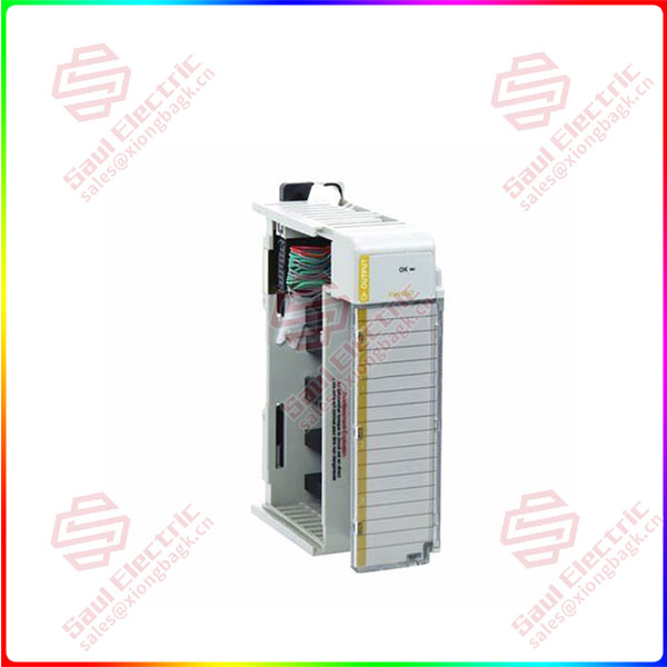
Essential details:1769-OF4 Isolated Analog Output Module
The following procedure lets you use the assembled modules as a template for drilling holes in the panel. If you have sophisticated panel mounting equipment, you can use the dimensional template provided on page 10. Due to module mounting hole tolerance, it is important to follow these procedures.
1. On a clean work surface, assemble no more than three modules.
2. Using the assembled modules as a template, carefully mark the center of all module-mounting holes on the panel.
3. Return the assembled modules to the clean work surface, including any previously mounted modules.
4. Drill and tap the mounting holes for the recommended M4 or #8 screw.
5. Place the modules back on the panel, and check for proper hole alignment.
DIN Rail Mounting
The module can be mounted using the following DIN rails:
• 35 x 7.5 mm (1.38 x 0.30 in.; EN 50 022 – 35 x 7.5)
• 35 x 15 mm (1.38 x 0.59 in.; EN 50 022 – 35 x 15)
Before mounting the module on a DIN rail, close the DIN rail latches. Press the DIN rail mounting area of the module against the DIN rail. The latches will momentarily open and lock into place.
Replacing a Single Module Within a System
1769-OF4CI
lf you need to inquire or purchase ,please send the product models to my email or call medirectly .
sunny He
[Email]sales@xiongbagk.cn
[Mobile]86-18059884797
[WhatsApp] 86-18059884797
[Skype]sales@saulcontrol.com
1769-OF4 Isolated Analog Output Module
The module can be replaced while the system is mounted to a panel (or DIN rail). Follow the steps below in order:
1. Remove power.
2. On the module to be removed, remove the upper and lower mounting screws from the module (or open the DIN latches by using a screwdriver).
3. Move the bus lever to the right to disconnect (unlock) the bus.
4. On the right-side adjacent module, move its bus lever to the right (unlock) to disconnect it from the module to be removed.
5. Gently slide the disconnected module forward.
If you feel excessive resistance, check that the module has been disconnected from the bus, and that both mounting screws have been removed (or DIN latches opened).
6. Before installing the replacement module, be sure that the bus lever on the module to be installed, and on the right-side adjacent module are in the unlocked (fully right) position.
7. Slide the replacement module into the open slot.
8. Connect the modules together by locking (fully left) the bus levers on the replacement module and the right-side adjacent module.
9. Replace the mounting screws (or snap the module onto the DIN rail). Module Spare/replacement Parts
• Terminal block, catalog number 1769-RTBN18 (1 per kit)
• Door, catalog number 1769-RD (2 per kit)
Grounding the Module
This product is intended to be mounted to a well-grounded mounting surface, such as a metal panel. Additional grounding connections from the module’s mounting tabs or DIN rail (if used), are not required unless the mounting surface cannot be grounded. Refer to Industrial Automation Wiring and Grounding Guidelines, publication 1770-4.1, for additional information.
 1 Year Warranty