1 Year Warranty
Description
Overview
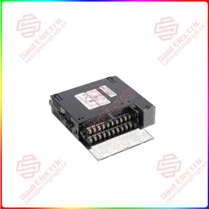
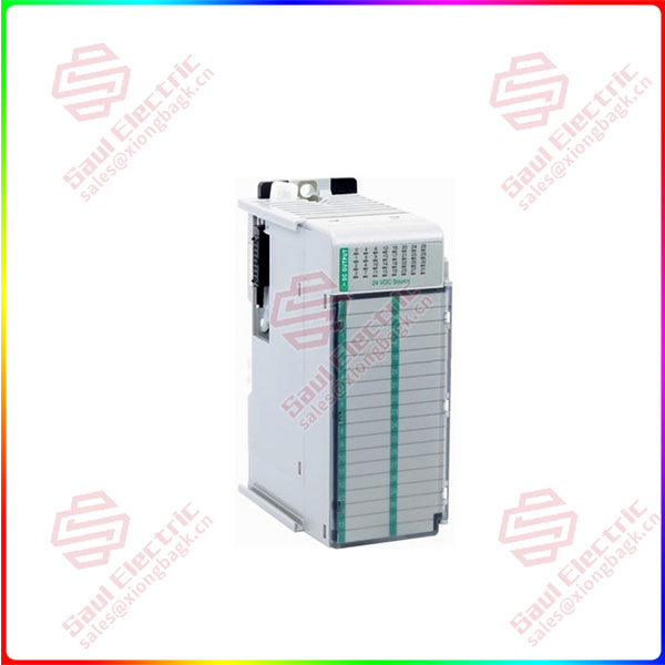
Essential details:1769-OB32 Compact 32-point Solid-state 24V dc Source Output Module
The module can be attached to the controller or an adjacent I/O module before or after mounting. For mounting instructions, see Panel Mounting on page 6, or DIN
Rail Mounting on page 8. To work with a system that is already mounted, see Replacing a Single Module within a System on page 8.
The following procedure shows you how to assemble the Compact I/O system.
1. Disconnect power.
2. Check that the bus lever of the module to be installed is in the unlocked (fully right) position.
3. Use the upper and lower tongue-and-groove slots (1) to secure the modules together (or to a controller).
4. Move the module back along the tongue-and-groove slots until the bus connectors (2) line up with each other.
5. Push the bus lever back slightly to clear the positioning tab (3). Use your fingers or a small screw driver.
6. To allow communication between the controller and module, move the bus lever fully to the left (4) until it clicks. Ensure it is locked firmly in place.
DIN Rail Mounting
The module can be mounted using these DIN rails:
35 x 7.5 mm (EN 50 022 – 35 x 7.5) or 35 x 15 mm (EN 50 022 – 35 x 15).
Before mounting the module on a DIN rail, close the DIN rail latches. Press the DIN rail mounting area of the module against the DIN rail. The latches will momentarily open and lock into place.
Replacing a Single Module within a System
The module can be replaced while the system is mounted to a panel (or DIN rail).
1. Remove power. See important note on page 4.
2. On the module to be removed, remove the upper and lower mounting screws from the module (or open the DIN latches using a flat-blade or phillips style screw driver).
3. Move the bus lever to the right to disconnect (unlock) the bus.
4. On the right-side adjacent module, move its bus lever to the right (unlock) to disconnect it from the module to be removed.
5. Gently slide the disconnected module forward. If you feel excessive resistance, check that the module has been disconnected from the bus, and that both mounting screws have been removed (or DIN latches opened).
6. Before installing the replacement module, be sure that the bus lever on the module to be installed, and on the right-side adjacent module are in the unlocked (fully right) position.
7. Slide the replacement module into the open slot.
8. Connect the modules together by locking (fully left) the bus levers on the replacement module and the right-side adjacent module.
9. Replace the mounting screws (or snap the module onto the DIN rail).
1769-OB32
lf you need to inquire or purchase ,please send the product models to my email or call medirectly .
sunny He
[Email] sales@xiongbagk.cn
[Mobile] 86-18059884797
[WhatsApp] 86-18059884797
[Skype] sales@saulcontrol.com
1769-OB32 Compact 32-point Solid-state 24V dc Source Output Module