Sale!

1769-IR6 Compact™ I/O 1769-IR6 RTD/resistance Input Module

The 1769-IR6 module receives and stores digitally converted analog data from RTDs or other resistance inputs, such as potentiometers. The module supports connections from any combination of up to 6 RTDs or other resistance inputs. See the input specifications on page 20 for supported RTD and resistance types, their associated temperature ranges, and the analog input signal ranges that each channel supports. Each of the 6 input channels is individually configurable for a specific input device and provides open- or short-circuit and over- or under-range indication.

Compact I/O is suitable for use in an industrial environment when installed in accordance with these instructions. Specifically, this equipment is intended for use in clean, dry environments (Pollution degree 2(1)) and to circuits not exceeding Over Voltage Category II(2) (IEC 60664-1).(3)

Categories: ,

Description

Overview


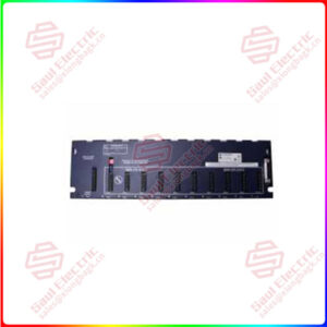
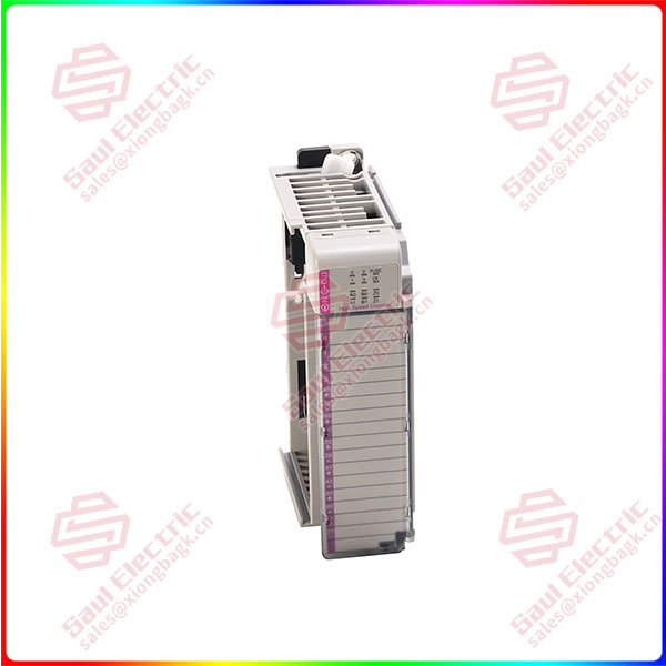
Essential details:1769-IR6 Compact™ I/O 1769-IR6 RTD/resistance Input Module

The 1769-IR6 module receives and stores digitally converted analog data from RTDs or other resistance inputs, such as potentiometers. The module supports connections from any combination of up to 6 RTDs or other resistance inputs. See the input specifications on page 20 for supported RTD and resistance types, their associated temperature ranges, and the analog input signal ranges that each channel supports. Each of the 6 input channels is individually configurable for a specific input device and provides open- or short-circuit and over- or under-range indication.

Compact I/O is suitable for use in an industrial environment when installed in accordance with these instructions. Specifically, this equipment is intended for use in clean, dry environments (Pollution degree 2(1)) and to circuits not exceeding Over Voltage Category II(2) (IEC 60664-1).(3)

The module can be attached to the controller or an adjacent I/O module before or after mounting. For mounting instructions, see “Panel Mounting” on page 6, or “DIN Rail Mounting” on page 7. To work with a system that is already mounted, see “Replacing a Single Module within a System” on page 7.
The following procedure shows you how to assemble the Compact I/O system.

1. Disconnect power.
2. Check that the bus lever of the module to be installed is in the unlocked (fully right) position.
3. Use the upper and lower tongue-and-groove slots (1) to secure the modules together (or to a controller).
4. Move the module back along the tongue-and-groove slots until the bus connectors (2) line up with each other.
5. Push the bus lever back slightly to clear the positioning tab (3). Use your fingers or a small screwdriver.
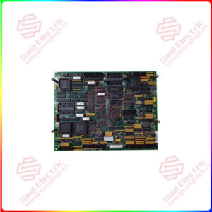
1769-IF16C

lf you need to inquire or purchase ,please send the product models to my email or call medirectly .

sunny  He

[Email] sales@xiongbagk.cn

[Mobile] 86-18059884797

[WhatsApp] 86-18059884797

[Skype] sales@saulcontrol.com

1769-IF16C Compact High-density Analog Input Modules

The following procedure allows you to use the assembled modules as a template for drilling holes in the panel. If you have sophisticated panel mounting equipment,
you can use the dimensional template provided on page 6. Due to module mounting hole tolerance, it is important to follow these procedures:
1. On a clean work surface, assemble no more than three modules.
2. Using the assembled modules as a template, carefully mark the center of all module-mounting holes on the panel.
3. Return the assembled modules to the clean work surface, including any previously mounted modules.
4. Drill and tap the mounting holes for the recommended M4 or #8 screw.
5. Place the modules back on the panel and check for proper hole alignment.
6. Attach the modules to the panel using the mounting screws.

DIN Rail Mounting
The module can be mounted using the following DIN rails: 35 x 7.5 mm (EN 50 022 – 35 x 7.5) or 35 x 15 mm (EN 50 022 – 35 x 15).
Before mounting the module on a DIN rail, close the DIN rail latches. Press the DIN rail mounting area of the module against the DIN rail. The latches will momentarily open and lock into place.
Replacing a Single Module within a System
The module can be replaced while the system is mounted to a panel (or DIN rail). Follow these steps in order:
1. Remove power. See important note on page 3.
2. On the module to be removed, remove the upper and lower mounting screws from the module (or open the DIN latches using a flat-blade or phillips-style screwdriver).
3. Move the bus lever to the right to disconnect (unlock) the bus.
4. On the right-side adjacent module, move its bus lever to the right (unlock) to disconnect it from the module to be removed.
5. Gently slide the disconnected module forward. If you feel excessive resistance, check that the module has been disconnected from the bus and that both mounting screws have been removed (or DIN latches opened).