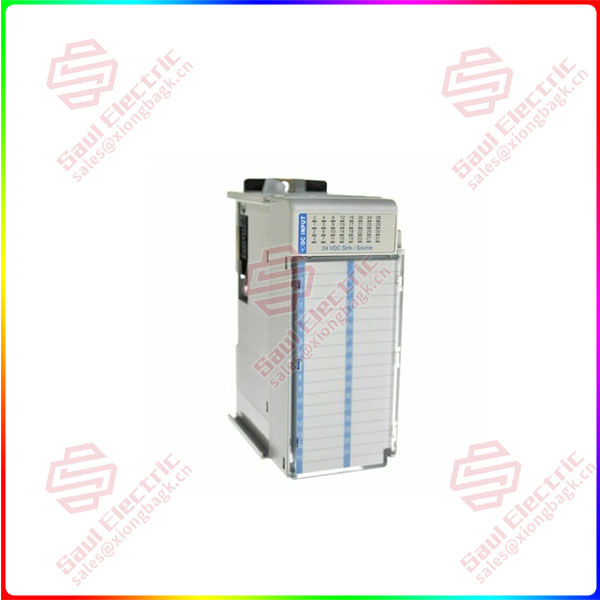
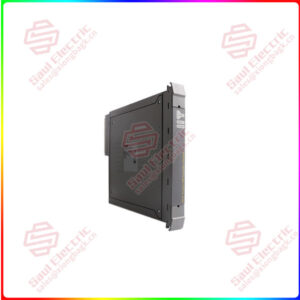
1769-IQ32 Compact 32-point 24V dc Sink/Source Input Module
Sale!
1769-IQ32 Compact 32-point 24V dc Sink/Source Input Module
Compact I/O is suitable for use in an industrial environment when installed in accordance with these instructions. Specifically, this equipment is intended for use in clean, dry environments (Pollution degree 2(1)) and to circuits not exceeding Over Voltage Category II(2) (IEC 60664-1).(3)
The module can be attached to the controller or an adjacent I/O module before or after mounting. For mounting instructions, see Panel Mounting on page 6, or DIN Rail Mounting on page 8. To work with a system that is already mounted, see Replacing a Single Module within a System on page 8.
The following procedure shows you how to assemble the Compact I/O system.
Essential details:1769-IQ32 Compact 32-point 24V dc Sink/Source Input Module
Compact I/O is suitable for use in an industrial environment when installed in accordance with these instructions. Specifically, this equipment is intended for use in clean, dry environments (Pollution degree 2(1)) and to circuits not exceeding Over Voltage Category II(2) (IEC 60664-1).(3)
The module can be attached to the controller or an adjacent I/O module before or after mounting. For mounting instructions, see Panel Mounting on page 6, or DIN Rail Mounting on page 8. To work with a system that is already mounted, see Replacing a Single Module within a System on page 8.
The following procedure shows you how to assemble the Compact I/O system.
1. Disconnect power.
2. Check that the bus lever of the module to be installed is in the unlocked (fully right) position.
3. Use the upper and lower tongue-and-groove slots (1) to secure the modules together (or to a controller).
4. Move the module back along the tongue-and-groove slots until the bus connectors (2) line up with each other.
5. Push the bus lever back slightly to clear the positioning tab (3). Use your fingers or a small screw driver.
6. To allow communication between the controller and module, move the bus lever fully to the left (4) until it clicks. Ensure it is locked firmly in place.
7. Attach an end cap terminator (5) to the last module in the system by using the tongue-and-groove slots as before.
8. Lock the end cap bus terminator (6).
1769-IQ32
lf you need to inquire or purchase ,please send the product models to my email or call medirectly .
sunny He
[Email]sales@xiongbagk.cn
[Mobile]86-18059884797
[WhatsApp] 86-18059884797
[Skype]sales@saulcontrol.com
1769-IQ32 Compact 32-point 24V dc Sink/Source Input Module
Locate holes every 17.5 mm (0.689 in.) to allow for a mix of single-wide and one-and-a-half-wide modules (e.g., 1769-OA16).
Panel Mounting Procedure Using Modules as a Template
This procedure lets you use the assembled modules as a template for drilling holes in the panel. If you have sophisticated panel mounting equipment, you can use the dimensional template provided on page 7. Due to module mounting hole tolerance, it is important to follow these procedures:
1. On a clean work surface, assemble no more than three modules.
2. Using the assembled modules as a template, carefully mark the center of all module-mounting holes on the panel.
3. Return the assembled modules to the clean work surface, including any previously mounted modules.
4. Drill and tap the mounting holes for the recommended M4 or #8 screw.
5. Place the modules back on the panel, and check for proper hole alignment.
6. Attach the modules to the panel using the mounting screws.
DIN Rail Mounting
The module can be mounted using these DIN rails:
35 x 7.5 mm (EN 50 022 – 35 x 7.5) or 35 x 15 mm (EN 50 022 – 35 x 15).
Before mounting the module on a DIN rail, close the DIN rail latches. Press the DIN rail mounting area of the module against the DIN rail. The latches will momentarily
open and lock into place.
Replacing a Single Module within a System
The module can be replaced while the system is mounted to a panel (or DIN rail).
1. Remove power. See important note on page 4.
2. On the module to be removed, remove the upper and lower mounting screws from the module (or open the DIN latches using a flat-blade or phillips style screw driver).
3. Move the bus lever to the right to disconnect (unlock) the bus.
4. On the right-side adjacent module, move its bus lever to the right (unlock) to disconnect it from the module to be removed.
5. Gently slide the disconnected module forward. If you feel excessive resistance, check that the module has been disconnected from the bus, and that both mounting screws have been removed (or DIN latches opened).
NOTE: It may be necessary to rock the module slightly from front to back to remove it, or, in a panel-mounted system, to loosen the screws of adjacent modules.
6. Before installing the replacement module, be sure that the bus lever on the module to be installed, and on the right-side adjacent module are in the unlocked (fully right) position.
7. Slide the replacement module into the open slot.
 1 Year Warranty