1746-P4 1746-P1 1746-P2 1746-P3 SLC 500 Power Supplies
Sale!
1746-P4 1746-P1 1746-P2 1746-P3 SLC 500 Power Supplies
To connect up to three SLC 500 chassis together, install the chassis interconnect cable before installing the power supply.
Place the input voltage jumper to match the input voltage. (This does not apply to the 1746-P3, 1746-P5, 1746-P6, and 1746-P7 power supplies, which do not have a jumper.)
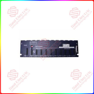
. Connect the ground screw of the power supply to the nearest ground or ground bus. Use a 1.68 mm (#14 AWG) 75° Copper wire (Category 1 per Industrial Automation Wiring and Grounding Guidelines, publication 1770-4.1) and keep the leads as short as possible. The 1746-P4 is shown below.
Essential details:1746-P4 1746-P1 1746-P2 1746-P3 SLC 500 Power Supplies
To connect up to three SLC 500 chassis together, install the chassis interconnect cable before installing the power supply.
Place the input voltage jumper to match the input voltage. (This does not apply to the 1746-P3, 1746-P5, 1746-P6, and 1746-P7 power supplies, which do not have a jumper.)
. Connect the ground screw of the power supply to the nearest ground or ground bus. Use a 1.68 mm (#14 AWG) 75° Copper wire (Category 1 per Industrial Automation Wiring and Grounding Guidelines, publication 1770-4.1) and keep the leads as short as possible. The 1746-P4 is shown below.
Your SLC 500 power supply can be damaged by voltage surges when switching inductive loads such as motors, motor starters, solenoids, and relays. To avoid damage to your SLC 500 power supply in these applications, use an isolation transformer to isolate the power supply from harmful voltage surges.
1746-P4
lf you need to inquire or purchase ,please send the product models to my email or call medirectly .
sunny He
[Email]sales@xiongbagk.cn
[Mobile]86-18059884797
[WhatsApp] 86-18059884797
[Skype]sales@saulcontrol.com
1746-P4 1746-P1 1746-P2 1746-P3 SLC 500 Power Supplies
This information describes special wiring considerations for the 1746-P3 power supply that are not labeled as revision (REV) B.
SLC 500 series A chassis (1746-A4, 1746-A7, 1746-A10, and 1746-A13) manufactured before November 1992 have a resistor between the logic ground and chassis ground as the drawing on the following page illustrates. This resistor could be damaged if the wiring recommendation described within the attention box above is not followed. See the figure on the following page for the location of the resistor. SLC 500 series A chassis (1746-A4, 1746-A7, 1746-A10, and 1746-A13) with a manufacture date of November 1992 or later do not have this resistor. SLC 500 series B chassis have a 1 MΩ resistor that limits the current between logic ground and chassis ground.
(Optional) For the 1746-P1, 1746-P2, 1746-P4, 1746-P5, and 1746-P6 power supplies, use PWR OUT +24V dc and PWR OUT COM terminals to power 24V dc sensors and loads. The terminals on the 1746-P1, 1746-P2, 1746-P5, and 1746-P6 power supplies provide an isolated, non-fused 200 mA, 24V dc power supply. The terminals on the 1746-P4 power supply provide an isolated, non-fused 1A, 24V dc power supply. (The 1746-P3 and 1746-P7 power supplies do not provide for an external power source.)
 1 Year Warranty