Sale!

1746-OB16 1746-OB16E 1746-OBP8 SLC 500 Digital I/O Modules

Follow these steps to install the module:
1. Disconnect power.
2. Align the circuit board of modulewich the chassis card guide. (A)

3. Slide the module into the chassisuntil the bottom tabs lock into place.B
4,Route the wires down and away fromthe module, securing them with chewire tie. (C)
5,Cover all unused slots with CardSlot Filler, catalognumber 1746-N2to keep the chassis free from debris.

6. To remove che module, press andhold the module relcase located oneach self-locking tab, and slide chemodule out of the chassis slot. (D)

Categories: ,

Description

Overview


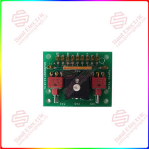
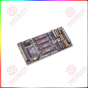
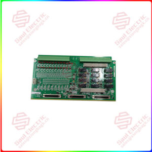
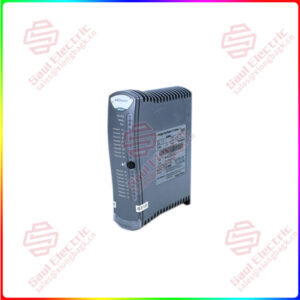
Essential details:1746-OB16 1746-OB16E 1746-OBP8 SLC 500 Digital I/O Modules

Follow these steps to install the module:
1. Disconnect power.
2. Align the circuit board of modulewich the chassis card guide. (A)

3. Slide the module into the chassisuntil the bottom tabs lock into place.B
4,Route the wires down and away fromthe module, securing them with chewire tie. (C)
5,Cover all unused slots with CardSlot Filler, catalognumber 1746-N2to keep the chassis free from debris.

6. To remove che module, press andhold the module relcase located oneach self-locking tab, and slide chemodule out of the chassis slot. (D)

The fuse on the 1746-OBP16 and 1746-OVP16 modules (shown on Location of Jumpers and Fuses for 1746-OBP16 and 1746-OVP16 Modules on page 9) provides short-circuit protection for 13 mm2 (16 AWG) or larger wiring to external loads. In the event of a short circuit on an output channel, it is likely that the transistor associated with that channel will be damaged. In this event, the module should be replaced or the load moved to a spare output channel.
The fuse does not provide overload protection. In the event of an overload on an output channel, it is likely that the fuse will not blow and the transistor associated with that channel will be damaged. To provide overload protection for your application, user-supplied fuses should be installed externally and properly sized to match your individual load characteristics.
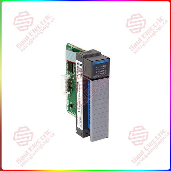
1746-OB16

lf you need to inquire or purchase ,please send the product models to my email or call medirectly .

sunny  He

[Email] sales@xiongbagk.cn

[Mobile] 86-18059884797

[WhatsApp] 86-18059884797

[Skype] sales@saulcontrol.com

1746-OB16 1746-OB16E 1746-OBP8 SLC 500 Digital I/O Modules

A fuse is provided on each common of the 1746-OAP12 module (shown on Location of Jumpers and Fuses for 1746-OAP12 Module on page 10) for a total of two fuses. The fuses are designed to protect the module from short-circuit conditions. The fuse does not provide overload protection. In the event of an overload on an output channel, it is likely that the fuse will not blow and the output device associated with that channel will be damaged. To provide overload protection for your application, user-supplied fuses should be installed externally.
The recommended fuse for overload protection is SAN-O HT. Select the fuse rating according to your load. Do not use HT fuses rated higher than 2.0 Amps.

The Processor Fault position for JP1 is shown on the following page. For this JP1 configuration, the processor generates a nonrecoverable error for all SLC 500 processors. For a nonrecoverable error, note the following:
• Processor operation halts and the processor fault light flashes.
• All outputs are reset to OFF.
• The processor major fault bit S:1/13 is set.
• Monitor processor status file word S:6 for error code xx58 for SLC 500, and SLC 5/01 processors, and error code xx60 for SLC 5/02 and later processors.

For additional information on processor fault codes and user-fault routines refer to the following publications:
• Your programming device’s reference manual
• HHT User Manual, publication 1747-NP002:
• Chapter 28, Troubleshooting Faults
• Chapter 29, Understanding the Fault Routine