1 Year Warranty
Description
Overview
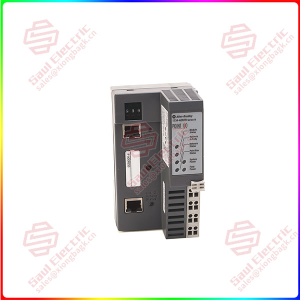
Essential details:1734-AENT POINT I/O Ethernet I/P communication adapter Allen-Bradley
Technical Specifications for 1734-AENT
| Manufacturer | Rockwell Automation |
| Power Dissipation | 5.2 Watts (at 28.8 Volts) |
| POINTBus Current | 1000 milliamps |
| Power Consumption | 10.4 W @ 28.8V DC |
| Field Side Power | 400 milliamps |
| Topologies: | Star, Tree |
| Indicators | 3 red/green status indicators (on CPU): – Module status – Network status – POINTBus status 1 green status indicator on CPU: – Network activity 2 green power supply status indicators on DC-DC Converter: – System power (5V DC to POINTBus Out) – Field power (24V DC from Field In) |
| Supported Topologies | Star / Tree topologies |
| Communication Rate | 10/100 Mbits/s, half or full-duplex. |
| I/O Points, max. | 504 |
| I/O Module Capacity | 63 modules |
| No. of Ports | 1 |
| Product Type: | Communications |
| Product Family: | 1734 POINT I/O |
| Brand | Allen-Bradley |
The Allen-Bradley 1734-AENT is a POINT I/O Ethernet I/P communication adapter. This module is part of the bulleting 1734 POINT I/O Product family, enabling a POINT I/O rack to exchange real-time I/O data to the master controller in the Ethernet I/P network. It interfaces POINT I/O modules and facilitates transfer not only I/O but diagnostic information as well.
The 1734-AENT has a built-in Ethernet communication port, with RJ45 physical interface. This port supports transmission speed of 10/100 Mbps in half or full-duplex operation. It comes with auto-negotiation capability, eliminating the need to specifically set the transmission rate of the module. The 1734-AENT connects the POINT I/O rack in star and tree topology. It uses Category 5 cable, Shielded or unshielded wires, installed with RJ45 connector on both ends of the cable.
The 1734-AENT is provided with LED status indicators used for monitoring the operation of the module and diagnosing in the event of module fault. These indicators include Three (3) red/green status indicators located on the CPU to indicate Module, Network and POINTBus status.
The 1734-AENT is supplied with 24V DC voltage to energize the module with field bus power supply current of 10 A. The acceptable supply range of the 1734-AENT is 10-28.8VDC. The 1734-AENT has an integral Reverse Polarity Protection.
The 1734-AENT may be installed up to 63 POINT I/O modules or maximum of 504 input and output points. Expansion power supplies may be installed to provide sufficient POINTBus current to the modules installed in the POINT I/O rack. One (1) expansion power supply may supply power to a maximum of 17 modules.
1734-AENT
Superiority products 1734-AENT POINT I/O Ethernet I/P communication adapter Allen-Bradley
- This module can communicate with other POINT I/O modules on the same DIN rail. The IP addresses in this module are assigned via the standard BootP or DHCP tools. The Allen-Bradley 1734-AENT can support connections from several controllers simultaneously. The 1734-AENT adapter has 24 Volts DC input voltage rating and an inrush current of 6 A, maximum with dimensions of 30x 2.16 x 5.25 inches. This Ethernet/IP adapter module has an RJ-45, Category 5 Ethernet Connector.
The Allen-Bradley 1734-AENT adapter acts as a bridge between the POINT I/O module and the network, so the user control real-time I/O data. This module has messaging data support for configuration and programming information (these are also known as explicit messages). The 1734-AENT adapter uses a Common Industrial Protocol (CIP). CIP is the application layer protocol that is specified for Ethernet/IP or Ethernet Industrial Protocol and for the ControlNet network and DeviceNet. This is a message-based protocol that implements a relative path for sending messages from the device in a system to the consuming device. When you apply power to the POINT I/O system and create an I/O connection, transition the output to Idle State, apply the Idle State data before switching to RUN mode. This happens even when the controller makes the connection in RUN mode.