1 Year Warranty
Description
Overview
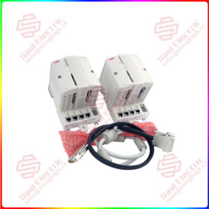
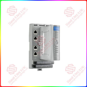
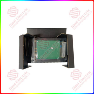
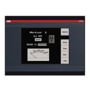
Essential details:0090-76110 Isolated Wide Range Power Board AMAT
Combinatorial logic
The combinatorial logic controller is composed of sequential circuit, instruction decoding circuit and combinatorial logic circuit. Through the instruction decoder to determine the current execution of the instruction, combined with the timing circuit generated by the beat, together as the input result of the combinative logic circuit output corresponding control signals. Combinatorial logic controller is composed of complex combinatorial logic gate circuit and flip-flop, and has high execution speed, so it is widely used in computer structures such as RISC. [1]
Design steps:
1. Design the instruction system of the machine: specify the types of instructions, the number of instructions and the format and function of each instruction;
2. Preliminary overall design: such as register setting, bus arrangement, computer design, connection relationship between components, etc.;
3. Draw instruction flow chart: mark the operation of each instruction at what time and what part;
4. Arrange operation schedule: that is, decompose each operation into micro-operation according to the instruction flow chart, and list the micro-operation to be carried out by the machine according to the time period;
5, list the microoperation signal expression, simplification, circuit realization.
0090-76110
Sales Manager: Manager He
E-mail number: sales@saulcontrol.com
skypel wechat: +86-18059884797
Mobile phonelwechat: +86-18059884797
QQ:3095989363
Basic composition:
1. The instruction register is used to store the instructions being executed. The instruction is divided into two parts: the operation code and the address code. The operation code is used to indicate the operation nature of the instruction, such as addition, subtraction, etc. Address code gives the operand address of this instruction or information about forming the operand address (in this case, the address formation circuit is used to form the operand address). There is a kind of instruction called transfer instruction, it is used to change the normal order of execution of instructions, such instruction address code section gives the address of the instruction to be forwarded to execution.
2. Operation code decoder: used to decode the operation code of the instruction, generate the corresponding control level, and complete the function of analyzing the instruction.
3, timing circuit: used to generate time signal. In the microcomputer, the time marker signal generally has three levels: instruction cycle, bus cycle and clock cycle. Microoperation command generation The circuit generates various microoperation commands that complete the operations specified by the instruction. These commands are mainly based on the time stamp and the operational nature of the instruction. The circuit is actually the circuit realization of each microoperation control signal expression (A→L expression above), it is the most complex part of the combinational logic controller.
4. Instruction counter: used to form the address of the next instruction to be executed. Normally, instructions are executed sequentially, and instructions are stored sequentially in memory. So, in general, the address of the next instruction to be executed can be formed by adding 1 to the current address. The microoperation command “1” is used for this purpose. If a transfer instruction is executed, the address of the next instruction to be executed is the address to be transferred to. The address is in the address code field of the transfer instruction and is sent directly to the instruction counter.
Microprogram controller is proposed because combinatorial logic design is not easy to design, not flexible, not easy to modify and expand.
microprogram
The basic idea of microprogram control (microcode control for short) is to generate microoperation commands with microinstructions. The function of an instruction is completed by executing a series of basic operations, which are called microoperations. Each microoperation is executed under the control of corresponding control signals, which are called microcommands in microprogram design. Microprogram is a sequence of microinstructions, corresponding to the function of a machine instruction, each microinstruction is a 0/1 sequence, which contains several microcommands, it completes a basic operation or transmission function, sometimes also known as the microinstruction word, called controlword .
The composition of microprogram controller:
1. Control Memory is used to store microprograms corresponding to machine instructions. A decoder is used to form the entry address of a microprogram corresponding to a machine instruction. When each microinstruction of the microprogram corresponding to a machine instruction is taken out one by one and sent to the microinstruction register, the microoperation command will be issued according to the prior design, thus completing the function of a machine instruction. This is true for every machine instruction.
2. The width of microinstruction directly determines the width of microprogram controller. In order to simplify the control memory, some measures can be taken to shorten the width of the microinstruction. Such as the use of field decoding method one level segmentation decoding. Obviously, the control field of the microinstruction will be greatly shortened. Some micromanipulation commands to be generated at the same time cannot be arranged in the same field. To further shorten the control field, field decoding can also be designed to be two – or multilevel