1 Year Warranty

Description
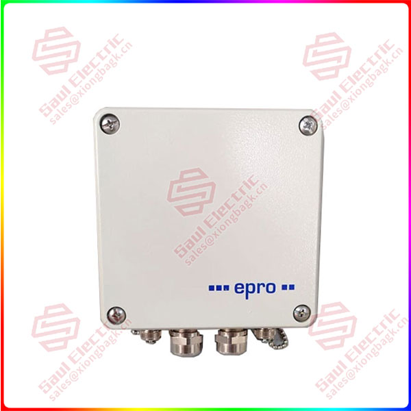
MMS3311 9100-00034-01 — Speed- and Key-Transmitter
Product Overview
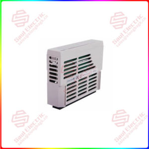
The MMS3311 9100-00034-01 is a speed and key-phase transmitter from EPRO GmbH, the German machine-monitoring specialist now part of Emerson, and belongs to the MMS 3000 transmitter system designed for monitoring and protecting turbo machinery. The module is ordered under the EPRO part number 9100-00034-01, which specifies the factory-configured hardware combination of the MMS3311 — in the same way every MMS 3000 transmitter is defined by its NC code rather than by the base name alone.
Its function is precise and narrow: it measures the rotational speed of a shaft and generates key-phase pulses for vibration analysis, using two independent eddy-current sensor channels. Channel 1 carries the speed measurement; channel 2 generates the key pulse, triggered by a key mark or trigger wheel on the rotor. Both channels operate independently, which lets one unit replace what conventionally required two separate instruments in a vibration rack.
The transmitter converts the raw proximity-probe signal into industrially usable values at the point of measurement: redundant 24V DC supply inputs, 0/4…20 mA parameter outputs, up to five configurable function outputs for alarms and machine states, and an RS 232 interface for configuration and data readout, with optional RS 485 or PROFIBUS DP for integration into plant control systems. Because it is mounted directly at the machine in an IP65 housing, the MMS3311 shortens sensor cable runs, removes the need for rack-mounted speed cards in the control room, and gives maintenance teams a self-supervising front end that reports its own health.
Technical Specifications
| 参数名称 | 参数值 |
|---|---|
| Product Model | MMS3311 9100-00034-01 (EPRO NC order number) |
| Manufacturer | EPRO GmbH (a brand of Emerson), Germany |
| Product Type | Speed- and key-transmitter, MMS 3000 series |
| Sensor Inputs | 2 independent channels, eddy current probes PR 6422 / 6423 / 6424 / 6425 |
| Speed Measuring Range | Freely configurable via software, max. 65535 rpm |
| Frequency Range | 0…20 kHz, automatic trigger-level setting |
| Current Outputs | 2 × 0/4…20 mA (or 20…4/0 mA), max. burden 500 Ω, short-circuit-proof |
| Function Outputs | Up to 5 configurable (opto-coupler / relay / photoMOS variants) |
| Data Interfaces | RS 232 standard; optional RS 485 (epro protocol V2.0) or PROFIBUS DP |
| Power Supply | Redundant 24V DC inputs, 18…31.2V, decoupled via diodes, max. 6 W |
| Operating Conditions | -20…+65 °C, IP65, shock 20 g / 2 ms, vibration 5 g @ 60 Hz |
| Housing / Certifications | Non-corroding diecast aluminum; CE, EMC per EN 55011 and EN 61326 |
MMS3311
Key Features and Advantages
Dual-channel independence: The two inputs operate independently, so speed measurement and key-phase generation run as separate functions within one unit. If one channel degrades, the other keeps delivering data, and the integrated supervision flags the fault instead of silently corrupting the signal.
Wide-range speed measurement with linear response: Linearity error is 0.25% at 25 °C excluding the sensor, and the measuring range is freely scalable up to 65535 rpm. The automatic trigger-level setting removes the traditional headache of adjusting probe trigger thresholds by hand when a machine’s vibration or offset changes.
Redundant and directional modes: With two speed sensors wired, the transmitter detects rotational direction through a function output and supports a redundant mode that switches automatically to the second sensor when the first fails. Zero-speed detection signals standstill — valuable for barring gear, clutch, and standstill interlock logic.
Self-supervising channel health: The internal supervision continuously checks the sensor cable for short circuit or breakage, monitors system voltages, and verifies that the input signal stays within its predefined range. On any detected fault, the Channel Clear output changes state and the 4…20 mA output drives to 0 mA, so a downstream PLC or DCS sees a defined fault condition rather than a false measurement.
Direct machine mounting with hardened construction: The diecast, non-corroding aluminum housing with IP65 protection and 20 g shock rating is built for the vibration and contamination found beside bearings and casings. Mounting the transmitter locally shortens probe cable runs and avoids the signal degradation of long unshielded paths back to a rack.
Flexible plant integration: Standard RS 232 handles configuration and live values; optional RS 485 with the epro protocol V2.0 or PROFIBUS DP connects the transmitter directly to host systems. The dual-current mode even splits one output range into two scaled sections, so a single 4…20 mA loop can carry both fine and coarse speed resolution.
Application Areas
The MMS3311 is used wherever a rotating shaft’s speed and phase reference must be measured at the machine and delivered to protection or automation logic. In steam and gas turbine installations, it supplies the speed signal used for run-up/run-down monitoring and generates the key phase that synchronizes vibration analysis and balancing measurements. In compressors and large fans, the function outputs carry overspeed, zero-speed, and standstill states directly to the interlock chain, eliminating the need for a separate speed relay in the control room.
In refineries, chemical plants, and power stations, the current outputs feed PLC and DCS systems over standard 0/4…20 mA loops, while the optional PROFIBUS DP or RS 485 link carries the same values into higher-level condition monitoring networks. Smaller plants with only a few measuring points use the transmitter as a standalone instrument, since no rack, carrier card, or separate power unit is required beyond the 24V DC feed.
Pumps, gearboxes, and auxiliary drives round out the typical population, often with a single MMS3311 covering both the speed input and the phase reference for a diagnostic system. Note that the transmitter itself is not approved for hazardous areas; where explosive atmospheres are present, the external-converter option moves the sensing electronics out of the classified zone while the transmitter stays in the safe area.
Related Products
- MMS 3311/010-000 (NC 9100-03081) — standard configuration of the same transmitter: internal converter, RS 232, common-ground current output, no function outputs, no display.
- MMS 3311/011-000 (NC 9100-03080) — same transmitter with 5 × opto-coupler function outputs for limit-value signaling.
- MMS 3120 — dual-channel axial position monitor in the same MMS 3000 transmitter family; also the housing reference used for external-converter variants of the MMS3311.
- PR 6422 — compact eddy current probe, one of the sensor family directly matched to the MMS3311 input channels.
- PR 6423 — eddy current probe for larger shaft diameters, with ±1.0% combined linearity when paired with the MMS3311.
- PR 6424 — companion probe in the same sensor series, listed with the transmitter’s input specification.
- PR 6425 — matching eddy current sensor for the MMS3311’s channel specification.
- MMS 3910 — configuration software for all MMS 3000 transmitters, delivered with the MMS Para Kit (9510-00027), ordered separately from the hardware.
Installation and Maintenance
Installation preparation: Commissioning may only be carried out by trained staff. Mount the MMS3311 directly at the machine, preferably with the cable glands pointing downwards so moisture cannot enter the housing. The maximum permissible mounting-surface temperature is 65 °C; if the transmitter is installed on 10 mm spacing bolts, the surface may reach 90 °C but the ambient operating range drops to -20…+45 °C, so verify the location’s actual heat load before fixing the bracket. Connect the eddy current probes through the two Lemo sockets, feed the 24V DC supply to both redundant inputs, and route the parameter and function output wiring through the M20 glands. Before energizing, load the standard configuration or the factory-set option via the MMS 3910 software and confirm the measuring range, trigger level, and alarm limits match the machine’s nominal speed and the protection philosophy of the plant.
Maintenance advice: Rely on the built-in supervision rather than periodic signal checks — it already detects broken or shorted sensor cables and out-of-range inputs. When the Channel Clear output changes state or a current output reads 0 mA, treat it as a fault indication and verify the sensor cable and gap first, since these account for most field problems. Inspect the Lemo connectors and cable glands during scheduled outages, keep the key mark or trigger wheel free of debris, and observe the torque and seating of all connectors after vibration-intensive operation. The transmitter is not field-repairable; failed units should be returned to the manufacturer. Keep one spare MMS3311 configured to the plant’s settings, since re-commissioning a replacement takes minutes with the MMS Para Kit at hand.
Product Warranty
The MMS3311 9100-00034-01 is supplied with the standard EPRO / Emerson warranty, backed by factory configuration according to the order number so that the delivered hardware matches the option combination the plant specified. Each unit ships with CE certification and EMC verification to EN 55011 and EN 61326, and documentation covering installation, configuration, and ordering options. For the large installed base of MMS 3000 systems, the supply chain provides both new and tested surplus stock, pre-shipment function verification against the customer’s NC code, and application support for configuration, spare provisioning, and migration — ensuring that speed and key-phase channels keep delivering defined, verifiable values to protection and automation logic for the life of the machine train.