1 Year Warranty

Description
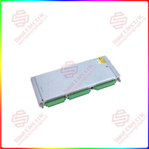
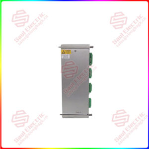
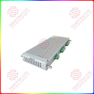
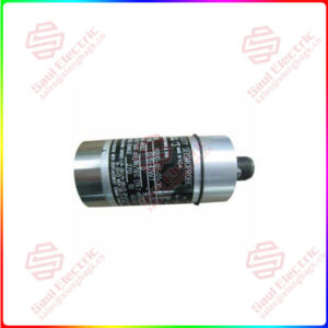
3500/22M 138607-01 — Standard Transient Data Interface (TDI)
Product Overview
The 3500/22M 138607-01 is the standard Transient Data Interface, or TDI, of the Bently Nevada 3500 Machinery Protection System, manufactured by Baker Hughes. Its role is precise: it is the bridge between the 3500 monitoring rack and the software that turns raw protection data into diagnostic insight — the System 1 condition monitoring and diagnostic platform and the 3500 System Configuration software. The TDI combines the functions of the older 3500/20 Rack Interface Module (RIM) with the data-collection capability of a communication processor such as TDXnet, so a single module both manages rack configuration and continuously streams transient waveform data to the host.
The TDI occupies the slot adjacent to the power supplies — Slot 1 — and every 3500 rack requires exactly one TDI or RIM. It reads steady-state values and dynamic waveform data from the M-series monitors in the rack (such as the 3500/42M and 3500/40M) and passes them over Ethernet to the host software, using either standard 10Base-T/100Base-TX copper or an optional 100Base-FX fiber link. Static data capture is standard; an optional Dynamic Data Enabling Disk extends the module to capture high-resolution transient waveforms for full startup, coastdown, and event analysis.
By design, the 3500/22M sits outside the critical protection path — its failure has no effect on the alarm and trip functions of the rack — which is exactly the architecture a protection system should have: diagnostics and configuration ride on the same rack without ever being allowed to weaken it.
Technical Specifications
| 参数名称 | 参数值 |
|---|---|
| Product Model | 3500/22M 138607-01 (standard TDI) |
| Manufacturer | Bently Nevada, a Baker Hughes business (USA) |
| Product Type | Standard Transient Data Interface (TDI), 3500 system |
| Power Consumption | 10.5 W |
| Front Panel Interface | USB-B, BN Host Protocol, 115.2 kbaud max, 5 m cable limit |
| Ethernet I/O | 10Base-T / 100Base-TX autosensing, RJ-45, 100 m max; optional 100Base-FX fiber to 2000 m |
| Keyphasor Inputs | Supports 4 system Keyphasor signals; 1–100,000 rpm (1–16 dynamic channels) |
| Waveform Data | 48 channels; synchronous 1024–16 samples/rev; asynchronous 800-line spectra, 10 Hz–30 kHz spans |
| System Contacts | Trip Multiply, Alarm Inhibit, Rack Reset; I/O OK relay 5 A @ 24 Vdc/120 Vac |
| Operating Environment | -30…+65 °C operating, -40…+85 °C storage, 95% RH noncondensing |
| Physical | 241.3 × 24.4 × 241.8 mm, 0.91 kg; 1 full-height front slot + 1 rear slot |
| Certifications | FCC Part 15; EMC/LVD (EN 61000-6-2/-6-4, EN 61010-1); CSA/NRTL/C and ATEX/IECEx options |
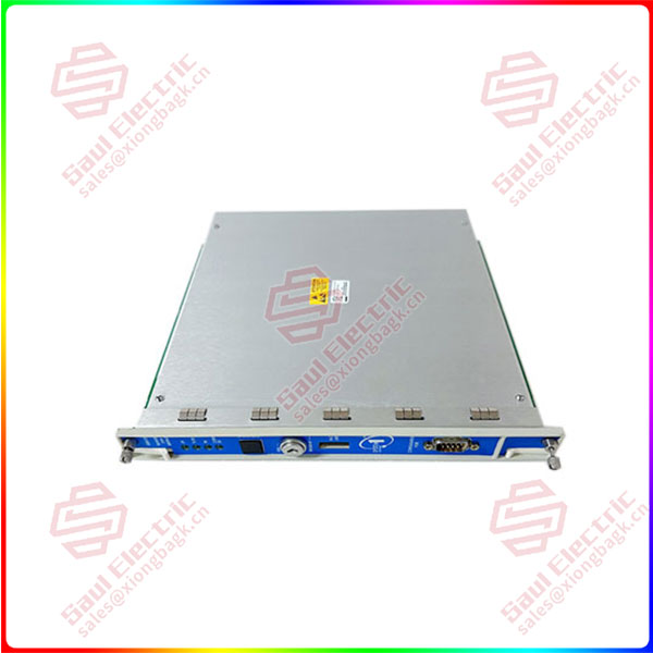
3500/22M 138607-01
Key Features and Advantages
Two legacy functions in one slot: The 3500/22M replaces both the RIM and a separate communication processor, freeing a rack slot and simplifying the configuration architecture. For plants upgrading an older rack, this consolidation is the difference between adding hardware and replacing it.
Full transient capture when enabled: With the Dynamic Data Enabling Disk, the TDI collects steady-state and transient waveforms — the data that diagnosis actually depends on: startup and coastdown records, orbit presentations from channel pairs, and high-resolution spectra captured at speed-triggered intervals.
Deliberately outside the protection path: The module has no effect on the normal alarm and trip operation of the rack. Its failure cannot compromise protection, which means diagnostic connectivity can be maintained, patched, and upgraded without changing the safety character of the installation.
Flexible network topology: Copper Ethernet to 100 m covers control-room distances; the 100Base-FX fiber option reaches 2000 m with full duplex multimode, which suits large plants and remote machine halls where copper cannot span the distance or the EMI environment is hostile.
Protocol support for the full software stack: BN Host Protocol serves the 3500 configuration, data acquisition, and display software, while the BN TDI Protocol feeds System 1 directly. The same module serves commissioning, online monitoring, and long-term diagnostic storage without separate gateways.
Engineered for event forensics: Alarm data capture stores pre- and post-event static values and waveforms — 10 minutes of one-second static data before an alarm, plus 2.5 minutes of waveform data at 10-second intervals — so the record that matters most to a post-trip investigation is already in the module’s memory when the engineer arrives.
Operational conveniences that matter in the field: A front-panel USB-B port simplifies configuration, the rack reset button clears latched alarms without rack power cycling, and the key-operated RUN/PROGRAM switch physically locks out unauthorized reconfiguration. The battery-backed clock is rated for 38 years at 50 °C while powered.
Certified for the same environments as the rack it serves: CSA/NRTL/C Class I Division 2 and ATEX/IECEx approvals, together with EMC and low-voltage compliance, let the TDI sit in the same cabinet as the protection modules without a separate enclosure or approval study.
Application Areas
The 3500/22M appears in every 3500 installation that needs more than alarms: steam and gas turbines, centrifugal compressors, generators, and large pumps where condition monitoring software must see the waveform behind every trip. During machine startup and coastdown, the TDI captures data at programmable speed and time increments, building the run-up records that reveal rubs, instabilities, and balance changes — records that protection monitors discard by design.
When an alarm occurs, the module’s pre- and post-event capture preserves the static values and waveforms surrounding the moment of the trip, giving diagnostics engineers the evidence needed to distinguish a genuine machine fault from a sensor or setpoint problem. Remote diagnostic centers connect to racks over Ethernet — copper within the plant, fiber across long distances — using the BN TDI protocol into System 1, which turns the collected transients into the diagnostic workflows that maintenance departments actually use.
In multi-rack plants, one TDI per rack consolidates configuration and data collection locally, while the Dynamic Data Enabling Disk allocates waveform channels across the fleet. And because the module is not part of the protection chain, plants can deploy it in the same classified cabinets as the monitors, backed by the same CSA, ATEX, or IECEx approval basis — diagnostics infrastructure that is as certifiable as the protection it serves.
Related Products
- 146031-01 — 10Base-T/100Base-TX Ethernet I/O module; the rear-slot companion for the 3500/22M copper link.
- 146031-02 — 100Base-FX fiber-optic Ethernet I/O module; same role for long-distance or EMI-hard fiber connections.
- 288055-01 — spare standard TDI module with USB cable, the replacement unit for a failed 138607-01.
- 3500/09 — Dynamic Data Enabling Disk; enables steady-state and transient waveform capture channels (up to 672 points per disk).
- 3500/20 — Rack Interface Module (RIM); the Slot 1 predecessor whose functions the 3500/22M absorbs.
- TDXnet — legacy communication processor; its data-collection role is integrated into the TDI.
- 3500/42M — M-series Proximitor/Seismic monitor whose steady-state and dynamic data the TDI continuously collects.
- 3500/40M — M-series position monitor; another data source read through the 3500/22M.
Installation and Maintenance
Installation preparation: The 3500/22M must occupy Slot 1 of the 3500 rack, adjacent to the power supplies, and every rack needs exactly one TDI or RIM. If upgrading from a RIM, follow the prescribed order strictly: remove the RIM first, then the RIM I/O, before installing the TDI I/O module and the TDI — leaving the old RIM I/O in the rack can damage the new module. Select the I/O module to match the network: 146031-01 for copper (shielded Category 5 cable, RJ-45, up to 100 m) or 146031-02 for multimode fiber with MT-RJ female connectors (up to 2000 m). Connect the front-panel USB-B port for configuration using the included 3 m cable (5 m maximum), and set the key-operated switch to the desired RUN or PROGRAM position before energizing, locking it in RUN once commissioning is complete.
Maintenance advice: Use the front-panel LEDs as the daily check — OK confirms module health, TX/RX confirms rack communication, TM indicates Trip Multiply mode, and CONFIG OK confirms the rack holds a valid configuration. Verify that the I/O module OK relay state matches the rack fault status and that System 1 connectivity over the BN TDI protocol is intact after any network change. The battery-backed clock is rated for 38 years at 50 °C while powered, but confirm the clock setting after long outages. Keep a documented spare 138607-01 with the matching I/O module, and check module-to-rack compatibility with Bently Nevada support before introducing TDI-equipped racks into mixed M-series populations.
Product Warranty
The 3500/22M 138607-01 is supplied with the Bently Nevada standard warranty, with new and tested surplus units verified against the official datasheet — power consumption, communication options, waveform sampling rates, and environmental limits — before shipment. Units carry the certification documentation appropriate to their approval option, including the CSA/NRTL/C Class I Division 2 or ATEX/IECEx marking and the referenced installation drawings, so a replacement preserves the rack’s approval basis. For the worldwide 3500 installed base, the supply chain provides the companion I/O modules, Dynamic Data Enabling Disks, and Ethernet cabling, together with application support for RIM-to-TDI upgrades and System 1 integration — keeping the interface between protection and diagnostics operational, documented, and supported for the life of the machine fleet.